
A relay amplification device and method for realizing long-distance distributed optical fiber sensing

A technology of distributed optical fiber and amplifying device, which is applied in the direction of measuring device, transmission system, electromagnetic wave transmission system, etc., can solve the problems of large power difference between excitation light and sensing light, no compensation of weak sensing light signal, etc., and achieve good realizability and reusability, good detection signal-to-noise ratio, good signal-to-noise ratio effect

Active Publication Date: 2019-06-25
ZHEJIANG UNIV
View PDF3 Cites 0 Cited by
  • Summary
  • Abstract
  • Description
  • Claims
  • Application Information

AI Technical Summary

Problems solved by technology

However, the relay uses a centralized optical amplification technology, which does not compensate for weak sensing optical signals, and is mainly suitable for distributed vibration sensors
[0005] Obviously, it is difficult to use the optical-electrical-optical regenerative relay mode in the distributed optical fiber sensing system, and the power difference between the excitation light and the sensing light is very large, it is difficult to use the bidirectional symmetrical optical amplification commonly used in optical communication systems for signal relay, which requires Appropriate optical amplification relay for strong excitation light and weak sensing light respectively

Method used


Image

  • A relay amplification device and method for realizing long-distance distributed optical fiber sensing
  • A relay amplification device and method for realizing long-distance distributed optical fiber sensing
  • A relay amplification device and method for realizing long-distance distributed optical fiber sensing

Examples


Embodiment 1

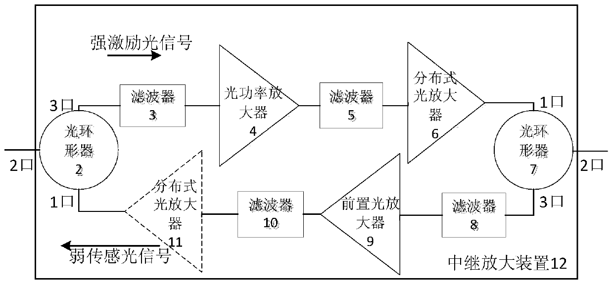
[0060] choose as figure 1 The shown relay amplification device is applied in Brillouin Optical Time Domain Reflectometer (BOTDR), and a 140km long-distance BOTDR sensing system with relay amplification device 12 is built. Such as Figure 5 As shown, the system includes: main parts such as BOTDR system 14, 70km sensing fiber 1, 70km sensing fiber 13 and relay amplifier 12; optical power amplifier 4 in relay amplifier 12 adopts erbium-doped fiber power amplifier, The distributed optical amplifiers 6 and 11 are Raman optical amplifiers, and the pre-optical amplifier 9 is an erbium-doped fiber pre-amplifier.

[0061] The BOTDR system 14 outputs the modulated pulse excitation light, the pulse excitation light enters the detection fiber as the detection signal source, and records the power P of the incident excitation light 0 The detection signal is injected into the relay amplifier 12 to amplify after passing through a section of 70km optical fiber 1, and the excitation light is ...

Embodiment 2

[0065] will select as figure 1 The relay amplification device shown is applied in a phase-sensitive optical time domain reflectometer sensing system (Φ-OTDR), and a 150km long-distance Φ-OTDR sensing system with a relay amplification device 12 is built. Such as Figure 6 As shown, the system includes: Φ-OTDR system 18, 50km optical fiber 15, two relay amplifiers 12, 50km optical fiber 16 and 50km optical fiber 17 and other main parts; the optical power amplifier 4 in the relay amplifier 12 adopts erbium-doped For the optical fiber power amplifier, the distributed optical amplifier 6 adopts a Raman optical amplifier, and the pre-optical amplifier 9 adopts an erbium-doped optical fiber pre-amplifier.

[0066] The Φ-OTDR system 18 outputs pulsed excitation light with strong coherence; after the excitation light is amplified, it is coupled into the detection fiber as a detection signal source, and the power P of the incident excitation light is recorded. 0 The pulsed excitation ...


PUM


Abstract

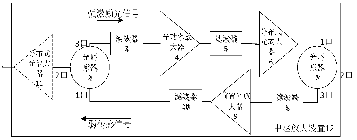
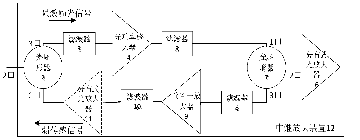
The invention discloses a relay amplifying device capable of achieving long-distance distributed optical fiber sensing. The relay amplifying device is used for improving sensing distance and performance of a distributed optical fiber sensing system. The relay amplifying device comprises an optical power amplifier, a front optical amplifier, a distributed optical amplifier, a filter and an optical circulator; the relay amplifying device can amplify strong excitation light and weak sensing light signals in a distributed optical fiber sensor respectively, the strong excitation light is amplified by the optical power amplifier and the distributed optical amplifier to obtain larger signal power again in a sensing midway, and a nonlinear effect caused by overlarge incident powder is effectively avoided; the weak sensing light signals are amplified by the front optical amplifier and the optional distributed optical amplifier, noise power is restrained through filtering, and the good signal-to-noise ratio is guaranteed. The relay amplifying device has a simple module structure and a wider work wave length and is suitable for varieties of distributed optical fiber sensing systems and favorable for improving the sensing distance and overall performance of the distributed optical fiber sensor.

Description

technical field [0001] The invention relates to the field of distributed optical fiber sensing, in particular to a relay amplifier and method for realizing long-distance distributed optical fiber sensing. Background technique [0002] Distributed sensing is regarded as one of the biggest advantages of fiber optic sensors, because it can not only realize the measurement of physical quantities distributed along the sensing fiber, but also give the location of physical quantity changes, so as to obtain the measured spatial distribution status and time-dependent changes. Information. The distributed optical fiber sensor developed by using this feature has high military and civilian value, and can be widely used in security systems, oil and gas pipeline monitoring, communication line safety monitoring and intelligent building health monitoring and other fields. [0003] Distributed optical fiber sensors generally use weak scattered light signal light (spontaneous nonlinear scatt...

Claims


Application Information

Patent Timeline
Patent Type & Authority Patents(China)
IPC IPC(8): H04B10/297H04B10/291
CPCG01H9/004H04B10/2912H04B10/2972H04B10/298
Inventor 宋牟平夏俏兰
Owner ZHEJIANG UNIV
Learn More