
An image lossless compression device and method

A lossless compression and image technology, applied in the direction of image communication, digital video signal modification, electrical components, etc., can solve the problems of increasing the cost of imaging system implementation, the difficulty of compression without information loss, and wasting storage capacity, so as to facilitate hardware transplantation, The hardware realizes the effect of low latency and high processing frequency

Active Publication Date: 2019-09-03
INST OF SEMICONDUCTORS - CHINESE ACAD OF SCI
View PDF5 Cites 0 Cited by
  • Summary
  • Abstract
  • Description
  • Claims
  • Application Information

AI Technical Summary

Problems solved by technology

[0004] At present, it is relatively difficult to perform real-time compression without information loss for such ultra-high bandwidth image data streams with high resolution and high frame rate (especially for image data streams exceeding 10Gbps).
Due to the limitation of high frame rate, high data bandwidth and processing capacity, most of the existing high-speed image acquisition systems directly store the original image data without any processing
Therefore, there is a large amount of redundant data in the image data, which actually wastes storage capacity, occupies additional transmission bandwidth, and greatly increases the implementation cost of the imaging system.

Method used


Image

  • An image lossless compression device and method
  • An image lossless compression device and method
  • An image lossless compression device and method

Examples


Embodiment 1

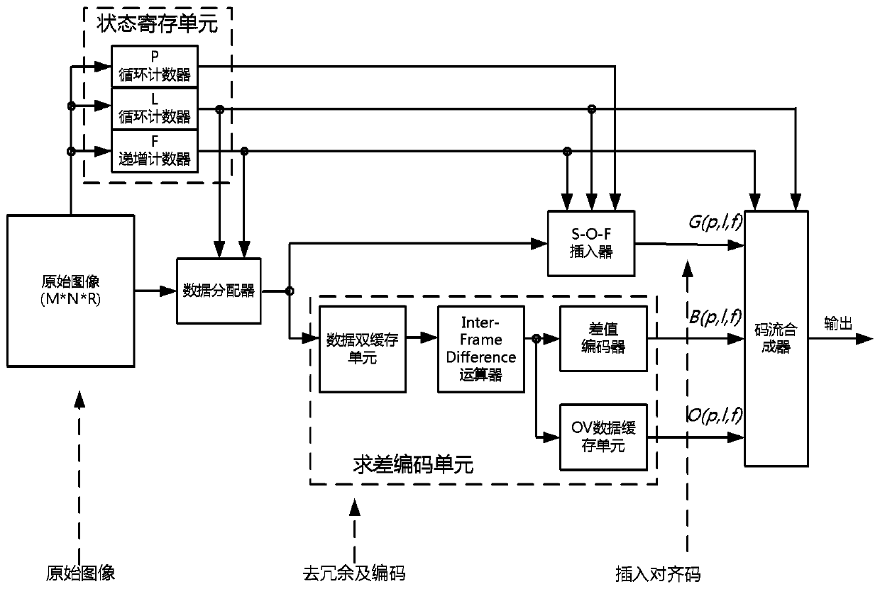
[0086] Such as figure 1 As shown, this embodiment proposes a lossless image compression device, which includes a state register unit, a data distributor, an S-O-F inserter, a difference encoding unit and a code stream synthesizer, wherein:

[0087] The state register unit includes a P loop counter, an L loop counter, and an F increment counter, which are mainly used to calculate and register the output status of the current image data, including the current pixel number, the current line number, and the current frame number.

[0088] The data distributor obtains the row number and frame number output by the state register unit, allocates and switches subsequent processing channels of the data stream, so that the data stream enters the channel of the S-O-F inserter and the channel of the difference encoding unit.

[0089] The S-O-F inserter also obtains the pixel serial number, row serial number, and frame serial number output by the state register unit. When the front dark pix...

Embodiment 2

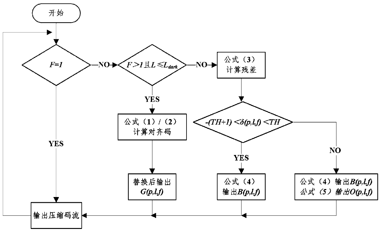
[0093] Such as figure 2 As shown, this embodiment proposes an image lossless compression method, using such as figure 1 As shown in the image lossless compression device, the compression method comprises the following steps:

[0094] Step 1. Keep the original data output without any processing on the first frame image;

[0095] Step 2. From the second frame of image, the dark pixel row in the frame of image data is calculated according to the formula (1) or formula (2) to obtain the alignment code value, and output after replacing the original value;

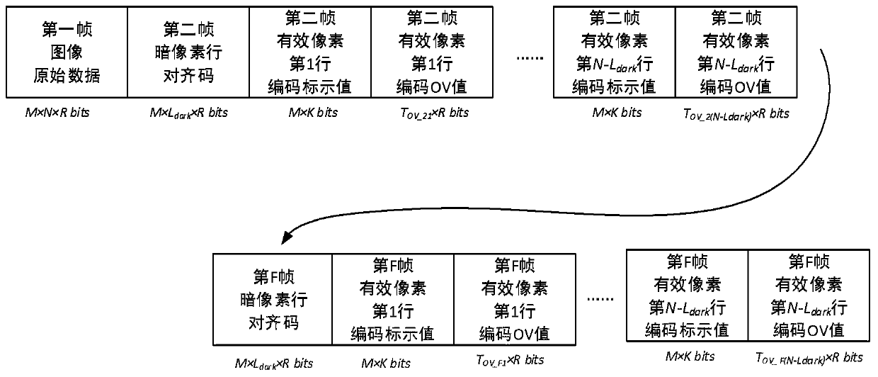
[0096] Step 3. Using the time correlation of the image frame sequence, the subsequent effective pixel rows in the second frame image and the corresponding rows in the previous image are calculated according to the formula (3) to obtain the image frame residual; the calculated residual, Compared with the preset threshold, and according to the formula (4) and formula (5) to obtain the coding mark value and the OV value, the codin...


PUM


Abstract

The invention discloses an image lossless compression device and method. The method comprises the steps that a first frame image is transmitted to a code stream synthesizer without being processed; a status register unit registers a pixel serial number, a line serial number and a frame serial number of an ith frame image, and a data distributor transmits dark pixel lines in the ith image data to an S-O-F inserter and outputs a code stream function of the ith frame image; the data distributor transmits other effective pixel lines except the dark pixel lines in the ith image data to a difference solution coding unit, calculates a preorder / postorder image frame residual of the ith frame image and codes the residual, thereby outputting a marking value and an OV value of each effective pixel line of the ith frame image; and the code stream synthesizer outputs the first frame image original data, the ith frame image code stream function, and the marking value and OV value of a jth line of the ith frame image. According to the method and the device, the time delay is relatively low; the relatively high processing dominant frequency can be realized, the parallelism degree is high; the lossless compression can be carried out on a plurality of frame images at the same time; hardware transplant of an algorithm is facilitated; and real-time compression under very high data bandwidth can be realized.

Description

technical field [0001] The present invention relates to an image information processing device and method, in particular to an image lossless compression device and method. Background technique [0002] Image sensors have been widely used in various fields such as scientific research, industrial production, medical and health care, and national defense and military affairs. With the continuous improvement of image resolution and image frame rate, human beings can observe more subtle object features or more short-term physical phenomena, which greatly enriches human observation methods and improves human cognition. [0003] However, with the rapid improvement of image performance parameters, it also brings a huge challenge that the amount of image data and data transmission bandwidth increase exponentially. Massive image data and ultra-high data transmission bandwidth have brought a series of technical difficulties for subsequent image transmission, storage and processing. ...

Claims


Application Information

Patent Timeline
Patent Type & Authority Patents(China)
IPC IPC(8): H04N19/136H04N19/17H04N19/423H04N19/436H04N19/85
Inventor 秦琦王加庆吴南健
Owner INST OF SEMICONDUCTORS - CHINESE ACAD OF SCI
Learn More