
End effecting mechanism for supporting endoscope in in-vitro minimally invasive surgery

An end-execution, minimally invasive surgery technology, applied in the field of medical robotics, can solve problems such as heavy weight of the end-effector, complex driving problems, complex kinematics, etc., to improve motion flexibility and accuracy, easy to control and implement, and reduce The effect of the moment of inertia

Active Publication Date: 2017-06-09
SHANGHAI UNIV OF ENG SCI
View PDF5 Cites 4 Cited by
  • Summary
  • Abstract
  • Description
  • Claims
  • Application Information

AI Technical Summary

Problems solved by technology

There are many classic cases in the development of telecentric mechanisms. For example, the five-link telecentric mechanism developed by the University of Tokyo is very easy to disassemble and assemble, which is convenient for robot disinfection, but its rigidity is slightly poor.
The spherical telecentric mechanism developed by the University of Washington uses the principle that the axis of the spherical joint passes through the center of the sphere to ensure the fixed-point four-degree-of-freedom movement of the end surgical instrument. This mechanism is very compact and easy to achieve miniaturization, but the drive problem of this mechanism Complex and difficult to control due to complex kinematics
There is also a compound parallel four-bar telecentric mechanism applied by da Vinci, which is very good in terms of stiffness and movement space, but it requires high machining accuracy, and at the same time, the weight of the end effector is large and the inertia is large.

Method used


Image

  • End effecting mechanism for supporting endoscope in in-vitro minimally invasive surgery

Examples


Embodiment

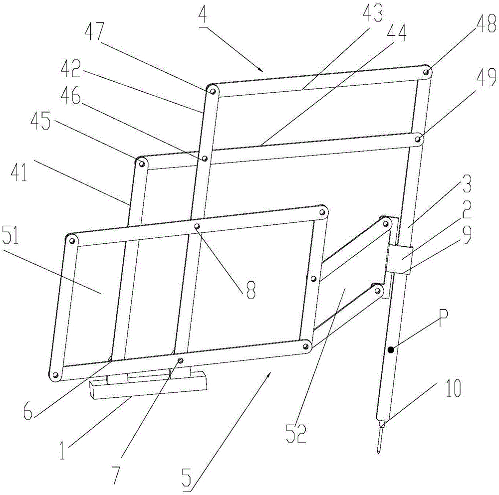
[0037] An end effector for supporting an endoscope in extracorporeal minimally invasive surgery, the structure of which is as follows: figure 1 As shown, it includes frame 1, slider 2, guide rail 3, first kinematic branch chain 4, second kinematic branch chain 5, first rotating pair 6, second rotating pair 7, third rotating pair 8, first moving pair 9 and the fourth rotating pair 10; the slider 2 is movably connected with the guide rail 3 through the first moving pair 9, and the first motion branch chain 4 is arranged on the frame 1 through the first rotating pair 6 and the second rotating pair 7; One end is movably connected with the guide rail 3, one end of the second kinematic branch chain 5 is connected with the frame 1 through the second rotating pair 7, and the other end is connected with the slider 2; through the active movement of the first kinematic branch chain, the second kinematic branch chain The active movement of the endoscope and the rotation movement of the en...


PUM


Abstract

The invention relates to an end effecting mechanism for supporting an endoscope in an in-vitro minimally invasive surgery. The mechanism comprises a frame, a slide block, a guide rail, a first moving branch chain and a second moving branch chain. The endoscope is connected below the guide rail through a rotary pair; the slide block slides up and down along the guide rail; one end of the first moving branch chain is movably connected to the guide rail while the other end of the first moving branch chain is movably connected to the frame through the rotary pair; one end of the second moving branch chain is connected to the slide block while the other end of the second moving branch chain is connected to the frame through the rotary pair; three-degree-of-freedom movement of the endoscope is realized by means of movements of the first moving branch chain and the second moving branch chain as well as a spin motion of the rotary pair of the endoscope. According to the effecting mechanism provided by the invention, the three-degree-of-freedom movement of two rotations and one movement around the rotating center at the distance of the endoscope is supported. Two motors controlling movement and pitch are placed on a base and are far from the end effecting device, so that the mass at the tail end of an endoscope surgical robot is lighter, the movement inertia is smaller, and the safety of the minimally invasive surgery is enhanced.

Description

technical field [0001] The invention relates to the field of medical robots, in particular to an end effector for supporting an endoscope in extracorporeal minimally invasive surgery. Background technique [0002] Parallel mechanisms are widely used in heavy-duty simulation equipment, robots, CNC machine tools, sensors and micro-manipulation and other fields. However, the drive units of the parallel mechanism are coupled, that is, the movement of the overall output platform of the parallel mechanism in any direction is the synthesis of the motions of all drive units, and the movement of each drive unit is combined with the overall movement of the parallel mechanism (i.e. input and output ) is non-linear. This characteristic leads to complex control of parallel mechanism, difficult calibration, and restricts the improvement of accuracy. Therefore, how to realize the decoupling of parallel mechanisms, simplify control and calibration, and improve motion accuracy has always b...

Claims


Application Information

Patent Timeline
IPC IPC(8): A61B17/00A61B34/30B25J9/00
CPCA61B17/00234B25J9/0045
Inventor 张帆张雪胡天宇王琰
Owner SHANGHAI UNIV OF ENG SCI
Learn More