Method for reducing deformation quantity of workpieces after laser cladding

A technology of laser cladding and deformation, which is applied in laser welding equipment, manufacturing tools, metal processing equipment, etc., can solve the problem of low surface flatness of materials, optimize surface flatness, improve processing quality and efficiency, reduce workload effect

Active Publication Date: 2017-06-09
江苏华博数控设备有限公司
View PDF9 Cites 11 Cited by
  • Summary
  • Abstract
  • Description
  • Claims
  • Application Information

AI Technical Summary

Problems solved by technology

[0006] The present invention aims to solve the problem of low surface flatness of materials in the existing laser cladding technology,

Method used


Image

  • Method for reducing deformation quantity of workpieces after laser cladding
  • Method for reducing deformation quantity of workpieces after laser cladding
  • Method for reducing deformation quantity of workpieces after laser cladding

Examples


Embodiment 1

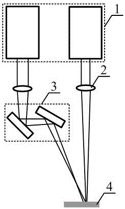
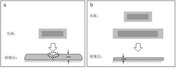
[0035] figure 1 and image 3 It shows a specific implementation of the method of reducing the deformation of the workpiece after laser cladding of the present invention, referring to figure 1 , the method for reducing the deformation of the workpiece after laser cladding in the specific embodiment of the present invention is applicable to the structure for reducing the deformation of the workpiece after laser cladding, including two stacked semiconductor lasers 1, two focusing mirrors 2, and a set of reflection Mirror group 3 and working surface 4.

[0036] The two semiconductor lasers 1 used are both made of one 915nm and one 976nm semiconductor laser stacked beams, each stack is composed of 20 bars, and the bars in the two stacked semiconductor lasers use fast and slow axes The collimating mirror collimates it, and the output power is 2kW.

[0037] In the structure for reducing the deformation of the workpiece after laser cladding applicable to the method of reducing the ...

Embodiment 2

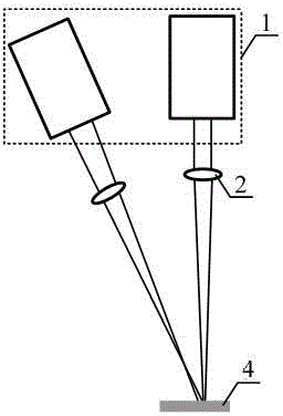
[0040] figure 2 Another specific implementation of the method for reducing the deformation of the workpiece after laser cladding of the present invention is shown. and figure 1 The specific implementation shown is different in that the reflector group 3 of the second optical path is removed, and the edge interval and irradiation angle of the two light spots on the working surface are adjusted directly by adjusting the position of the second semiconductor laser 1 . The working principle of the method for reducing the deformation of the workpiece after laser cladding in this embodiment is the same as figure 1 The specific embodiments shown are the same, so they will not be described here again.


PUM

PropertyMeasurementUnit
Wavelengthaaaaaaaaaa

Abstract

The invention relates to a method for reducing the deformation quantity of workpieces after laser cladding. The method comprises the steps that light outlets of two semiconductor lasers are placed downwards in parallel, two lasers are emitted in the same vertical plane in the same direction in parallel and are focused respectively, the focusing position of a second light spot is changed through the reflection action of a reflector set behind a focusing lens of a second light path, the two lasers act on the same work surface, a first light spot is used for cladding of the surface layer of material, the second light spot is used for secondary fusion of the surface layer of the material subjected to the cladding treatment, and therefore uneven portions on the surface of the material can be repaired. In the machining and repairing process, the size of the first light spot is smaller than the size of the second light spot. According to the method, the mode that only one light spot of a traditional laser cladding light source can be used for machining is changed, the two lasers are used for machining, the surface evenness of a cladding layer of the machined material is remarkably optimized, the machining quality and efficiency of laser cladding are greatly improved, and the subsequent machining is reduced.

Description

[0001] Technical field: [0002] The invention relates to the technical field of semiconductor lasers, in particular to a method for reducing the deformation of a workpiece after laser cladding. [0003] Background technique: [0004] Due to the advantages of small size, high electro-optical conversion efficiency and high reliability, semiconductor lasers have been gradually applied to the field of laser processing, including laser cutting, laser welding, laser cladding, laser 3D printing, etc., among which laser cladding technology is the core of laser processing. In an important application aspect, by irradiating the surface of the substrate with a high-energy-density laser beam, alloys with different compositions and properties are rapidly melted, expanded and solidified on the surface of the substrate, forming a completely different composition and alloy on the surface of the substrate. High performance alloy layer to modify the surface of the material, making the material ...

Claims


Application Information

Patent Timeline
IPC IPC(8): B23K26/064B23K26/067B23K26/21
CPCB23K26/0643B23K26/0673B23K26/21
Inventor 周成林朱洪波宁永强司松海
Owner 江苏华博数控设备有限公司
Why Eureka
Try Eureka