Cutting force prediction method considering tooth spacing angles, helical angles and eccentricity of cutter

A prediction method and inter-tooth angle technology, applied in manufacturing tools, measuring/indicating equipment, metal processing equipment, etc., can solve the problems of high experimental cost, high cost, low efficiency, etc., to improve efficiency, high accuracy, reduce cost effect

Active Publication Date: 2017-06-09
HUAZHONG UNIV OF SCI & TECH
View PDF4 Cites 16 Cited by
  • Summary
  • Abstract
  • Description
  • Claims
  • Application Information

AI Technical Summary

Problems solved by technology
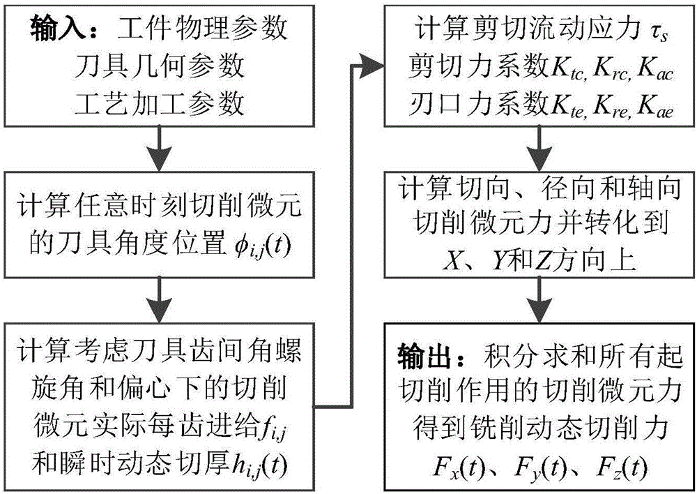
[0003] At present, those skilled in the art have done some research, such as literature "Budak, E., Y.Altintas, and E.J.A.Armarego."Prediction of milling force coefficients from orthogonal cutting data."Journal of Manufacturing Science and Engineering118.2(1996 ): 216-224.” discloses the use of a large number of orthogonal turning experiments to establish a cutting database, and then calibrates the shear angle, friction angle and shear stress in the model. This method requires a large number of cutting experiments, and the cost of the experiment is high. , and once the tool geometry changes, it needs to be re-calibrated; another example is the document "Wan, Min, et al."A unified instantaneous cutting force model for flat end mills with variable geometrie

Method used


Image

  • Cutting force prediction method considering tooth spacing angles, helical angles and eccentricity of cutter
  • Cutting force prediction method considering tooth spacing angles, helical angles and eccentricity of cutter
  • Cutting force prediction method considering tooth spacing angles, helical angles and eccentricity of cutter

Examples


specific example 1

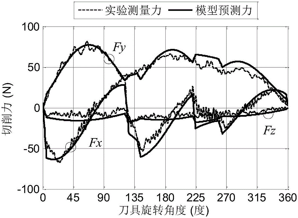
[0067] see image 3 , to predict the milling force of the cemented carbide tool on the aluminum alloy 6061-T6 in the five-axis machining center, which specifically includes the following steps:

[0068] (1) Determine the relevant parameters, the cemented carbide tool is a 3-tooth tool, where the tool diameter D = 8mm, the radial rake angle α n =5°, cutting edge radius r e =20um, inter-tooth angle φ pi =120° / 100° / 140°, helix angle β i =35° / 40° / 30°; spindle speed n=1000RPM, single tooth feed f z =0.1mm / z, axial depth of cut a p =0.5mm, radial cutting width a r = 7mm; After the tool is installed on the spindle, the laser displacement sensor is used to measure the tool eccentricity parameters as eccentricity distance ρ = 2.3mm and eccentricity angle λ = 32.3°, see Table 1 for details.

[0069] Table 1 Milling related parameters

[0070]

[0071](2) The dynamic force measuring instrument 9257A is used to collect the piezoelectric signal in the process of processing in rea...

specific example 2

[0089] see Figure 4 , the specific example 2 uses a 3-tooth variable inter-tooth angle cutter to perform down milling on aluminum alloy 6061-T6, and the physical parameters of the workpiece are the same as those in specific example 1; the inter-tooth angle φ pi =120° / 100° / 140°, the rest of the geometric parameters of the tool are the same as in the specific example 1; the process parameter is the axial depth of cut a p =1.5mm, radial cutting width a r =4mm, the eccentric distance ρ=4.3mm and the eccentric angle λ=20.6°, and the rest of the processing parameters are the same as those in the specific example 1.

[0090] Depend on Figure 4 It can be seen that the milling force prediction method considering the interdental angle, helix angle and eccentricity of the tool provided by the present invention is very close to the experimental value for the milling force prediction value of the variable interdental angle tool. It can be seen that the accuracy of the milling force pre...

specific example 3

[0092] see Figure 5 , the specific example 3 uses a 3-tooth variable helix angle tool for down milling of aluminum alloy 6061-T6, the physical parameters of the workpiece are the same as the specific example 1; the tool helix angle β i = 30° / 35° / 40°, the rest of the geometric parameters of the tool are the same as in Example 1; the process parameter is the axial depth of cut a p =1mm, radial cutting width a r =6mm, the eccentricity distance ρ=3.5mm and the eccentricity angle λ=30.8°, and the rest of the processing parameters are the same as those of the concrete example 1.

[0093] Depend on Figure 5 It can be seen that the milling force prediction method considering the interdental angle, helix angle and eccentricity of the tool provided by the present invention is very close to the experimental value for the milling force prediction value of the variable helix angle tool, and it can be seen that the accuracy of the milling force prediction method is relatively high , it...


PUM


Abstract

The invention belongs to the technical field related to cutting force prediction in a metal machining process, and discloses a cutting force prediction method considering tooth spacing angles, helical angles and eccentricity of a cutter. The method comprises the following steps: (1) determining physical parameters of a workpiece, geometrical parameters of the cutter and machining parameters of a process; (2) dividing the cutting area of the cutter into multiple sections of cutting micro-units, and calculating cutter angle positions of the cutting micro-units at any moment, wherein the cutter operates in the cutting area; (3) calculating actual each tooth feed and instantaneous dynamic cut thickness of the cutting micro-units; (4) calculating shear flow stress, a shear force coefficient and a cutting edge force coefficient; (5) calculating cutting micro-unit force of the cutting micro-units in the tangential, radial and axial directions of the cutter, and transforming the micro-unit force to the X, Y and Z axes of a machine tool coordinate system via a Cartesian coordinate system; and (6) summing integrals of all the cutting micro-unit force achieving a cutting effect on each cutting edge to obtain three-dimensional dynamic cutting force at any moment.

Description

technical field [0001] The invention belongs to the relevant technical field of milling force prediction in the metal processing process, and more specifically relates to a milling force prediction method considering the inter-tooth angle, helix angle and eccentricity of a tool. Background technique [0002] End milling mainly uses the bottom edge and circumferential side edge of the tool to remove excess material on the surface of the part to be processed. Due to its high material removal efficiency, it is widely used in the manufacture of parts in high-end fields such as aerospace. In order to meet the requirements of parts for processing efficiency and processing accuracy, milling cutters with special structures (such as profiling cutters and variable pitch milling cutters) are gradually being used in industrial production. Among them, the variable tooth pitch milling cutter has the functions of reducing cutting chatter, improving the processing surface quality, prolongin...

Claims


Application Information

Patent Timeline
IPC IPC(8): B23Q17/09B23Q17/22
CPCB23Q17/0933B23Q17/2233
Inventor 张小俭陈丁丁汉解亚昆
Owner HUAZHONG UNIV OF SCI & TECH
Why Eureka
Try Eureka