Cooling device of smoke cover dust remover

A technology for a cooling device and a dust collector, applied in the field of cooling devices, can solve the problems of affecting the service life of the dust collector, low efficiency, easy cracking of steel plates, etc., and achieve the effects of increasing the passing time, improving work efficiency, and improving speed.

Inactive Publication Date: 2017-06-13
CHONGQING ZON BON PHARMACY
View PDF0 Cites 3 Cited by
  • Summary
  • Abstract
  • Description
  • Claims
  • Application Information

AI Technical Summary

Problems solved by technology

[0002] Intermediate frequency induction furnaces are widely used in smelting, forging heating and heat treatment of non-ferrous metals. At present, the dust-containing flue gas in the intermediate frequency furnace needs to be cooled in the cooling tower through the fume hood, and then passed into the dust collector for flue gas treatment. However, Although the cooling tower in the past has an umbrella-shaped rotating cover, the flue gas can spirally rotate in the cooling tower to prolong the passage time in the cooling tower, but it still has a high temperature when entering the dust collector, which affects the service life of the dust collector. In the past, the flue gas cooled by the cooling tower needs to rise slowly into the dust collector by itself, the speed is slow and the efficiency is low. Some cooling towers using water cooling are prone to the technical problem that the steel plate is easy to crack due to the thermal expansion of the water body. For this reason , we propose a cooling device for a fume hood dust collector

Method used


Image

  • Cooling device of smoke cover dust remover

Examples


Embodiment Construction

[0012] The following will clearly and completely describe the technical solutions in the embodiments of the present invention with reference to the accompanying drawings in the embodiments of the present invention. Obviously, the described embodiments are only some, not all, embodiments of the present invention. Based on the embodiments of the present invention, all other embodiments obtained by persons of ordinary skill in the art without making creative efforts belong to the protection scope of the present invention.

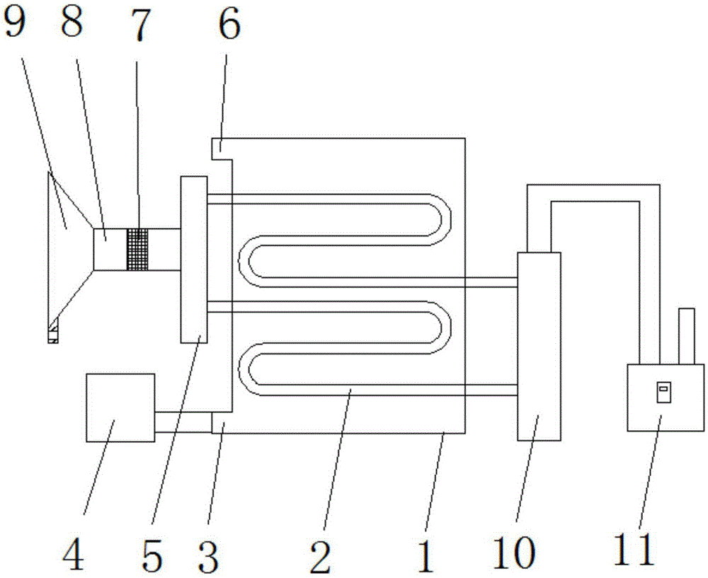
[0013] see figure 1 , the present invention provides a technical solution: a cooling device for a fume hood dust collector, including a water tank 1 and a fume hood 9, the fume hood 9 is in the shape of a round table, the side of the fume hood 9 is provided with a mounting block, and the mounting block is provided with The screw hole facilitates the fixing of the fume hood 9. The top surface of the fume hood 9 is connected to one end of the smoke guide pipe 8....


PUM


Abstract

The invention discloses a cooling device of a smoke cover dust remover. The cooling device comprises a water tank and a smoke cover. The smoke cover is in the shape of a circular truncated cone. An installing block is arranged on the side face of the smoke cover and provided with a screw hole. The top face of the smoke cover is connected with one end of a smoke guiding pipe. A smoke filter net is arranged in an inner cavity of the smoke guiding pipe. A flow dividing pipe is connected to the other end of the smoke guiding pipe. The side face of the flow dividing pipe is connected with cooling pipes which are S-shaped pipes, and no fewer than two cooling pipes are arranged and penetrate an inner cavity of the water tank. A water outlet is formed in the side face of the upper end of the water tank. A water inlet is formed in the side face of the lower end of the water tank. The water inlet is connected with a water outlet of a water pump through a water guiding pipe, and the ends, away from the flow dividing pipe, of the cooling pipes are connected with an air collecting pipe. The air collecting pipe is connected with an air inlet of an exhaust fan through an air guiding pipe. The cooling device of the smoke cover dust remover is simple in structure, high in cooling efficiency, capable of adjusting the work rate, convenient to use and reliable.

Description

technical field [0001] The invention relates to the technical field of cooling devices, in particular to a cooling device for a fume hood dust collector. Background technique [0002] Intermediate frequency induction furnaces are widely used in smelting, forging heating and heat treatment of non-ferrous metals. At present, the dust-containing flue gas in the intermediate frequency furnace needs to be cooled in the cooling tower through the fume hood, and then passed into the dust collector for flue gas treatment. However, Although the cooling tower in the past has an umbrella-shaped rotating cover, the flue gas can spirally rotate in the cooling tower to prolong the passage time in the cooling tower, but it still has a high temperature when entering the dust collector, which affects the service life of the dust collector. In the past, the flue gas cooled by the cooling tower needs to rise slowly into the dust collector by itself, the speed is slow and the efficiency is low. ...

Claims


Application Information

Patent Timeline
IPC IPC(8): F27D17/00
CPCF27D17/00Y02P10/25
Inventor 沙靖轶
Owner CHONGQING ZON BON PHARMACY
Why Eureka
Try Eureka