
A ring-shaped vehicle exhaust temperature difference power generation device

A technology of thermoelectric power generation and automobile exhaust, applied in the direction of generators/motors, electrical components, etc., can solve the problems of small space available at the exhaust pipe, large changes in water tank temperature, instability, etc., to save space position, increased contact area, and improved utilization

Inactive Publication Date: 2019-05-31
JIANGSU UNIV
View PDF2 Cites 0 Cited by
  • Summary
  • Abstract
  • Description
  • Claims
  • Application Information

AI Technical Summary

Problems solved by technology

[0004] At present, the patent No. CN201420869659.6 proposes a two-stage conversion series automobile exhaust air temperature difference power generation device. This device uses a heat collection system formed by connecting two heat collectors in series to absorb the heat of high-temperature exhaust gas. Although it can increase the heat The conversion utilization rate, but due to the small space available at the actual exhaust pipe, the arrangement of the device is difficult
Patent No. CN200910012468.1 proposes a water cooling method connected to the engine cooling cycle system. The coolant in this method is directly provided by the engine coolant. The coolant takes away the heat from the cold end while cooling the cold end. The heat passes through the engine cooling circulation system to further increase the temperature in the engine water tank. Because the water temperature in the engine water tank has a certain limit, and the coolant takes away the heat from the cold end of the thermoelectric power generation device, the temperature of the water tank changes greatly and is unstable. , so it is difficult to implement

Method used


Image

  • A ring-shaped vehicle exhaust temperature difference power generation device
  • A ring-shaped vehicle exhaust temperature difference power generation device
  • A ring-shaped vehicle exhaust temperature difference power generation device

Examples


Embodiment Construction

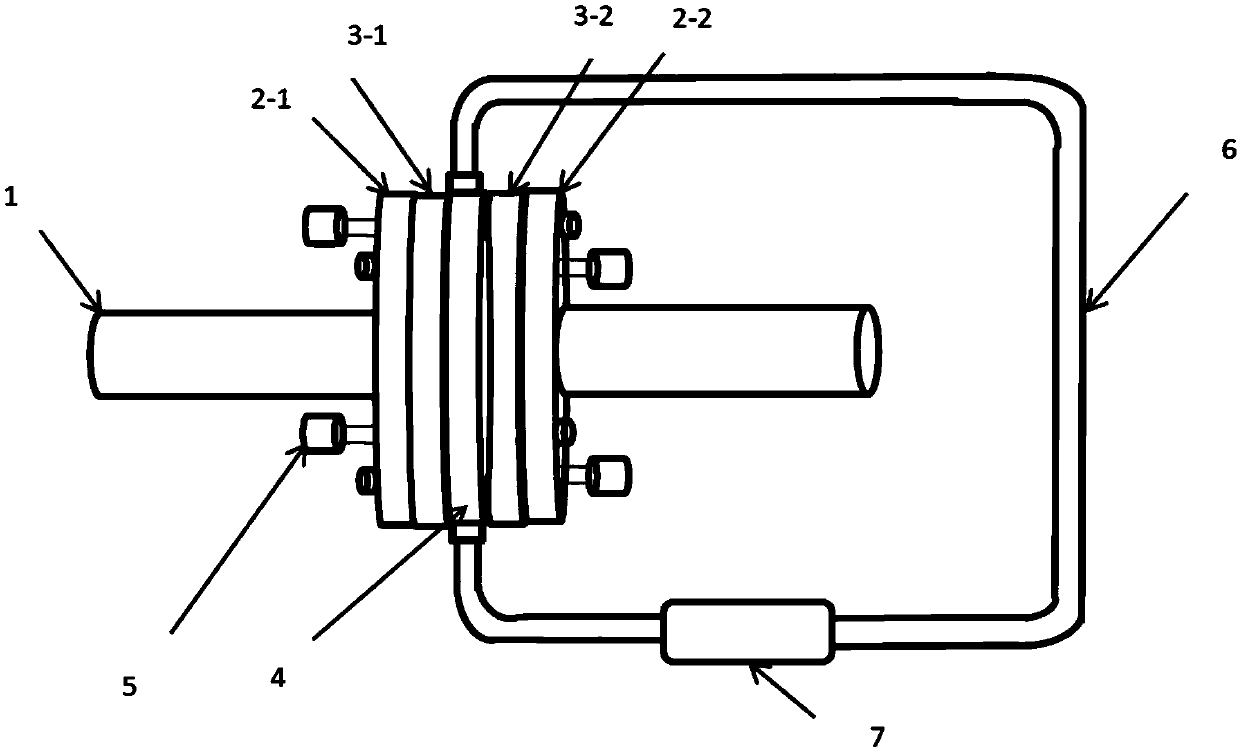
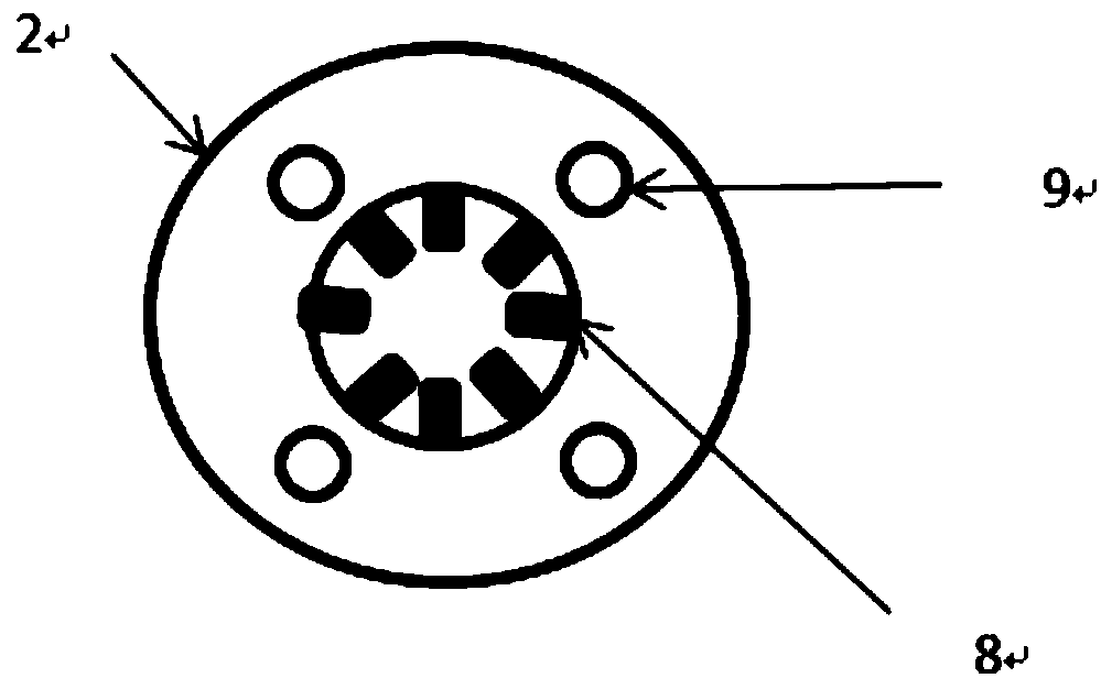
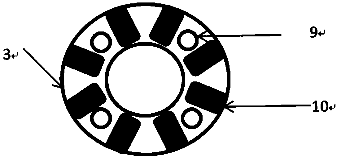
[0015] Such as figure 1 As shown, the present invention is a ring-shaped vehicle exhaust temperature difference power generation device, which includes a heat collection module 2, a thermoelectric power generation module 3, and a water cooling module 4.

[0016] The thermoelectric power generation device is installed in the position between the three-way catalytic converter and the muffler in the exhaust pipe 1, and the exhaust pipe 1 is sequentially connected to the first heat collection module 2-1, the first thermoelectric power generation module 3-1, and the water cooling module 4. The second thermoelectric power generation module 3-2, the second heat collection module 2-2;

[0017] The heat collection module 2 includes a first heat collection module 2-1 and a second heat collection module 2-2, and the thermoelectric power generation module 3 includes a first thermoelectric power generation module 3-1 and a second thermoelectric power generation module 3-2, and the thermoel...


PUM


Abstract

The invention relates to a ring-shaped automobile exhaust thermoelectric power generation device. The ring-shaped automobile exhaust thermoelectric power generation device mainly comprises a heat collecting module, a thermoelectric power generation module and a water cooling module, wherein heat collecting fins of the heat collecting module are mounted onto the inner surface of the outer ring of the heat collecting module in a ring-shaped mode for collecting heat of high-temperature exhaust; the thermoelectric power generation module generates electromotive force through temperature difference between both ends of the thermoelectric power generation module, namely, a hot end led by the exhaust and a cold end formed by cooling a thermoelectric power generation chip through the water cooling module, and then stores the electromotive force into a storage battery; the water cooling module forms a cooling liquid circulating system through a hydraulic pump to achieve temperature reduction of the cold end; the modules are fixed through bolts.

Description

technical field [0001] The invention relates to an annular automobile exhaust temperature difference power generation device, which belongs to the technical field of energy recovery and utilization of automobile exhaust. Background technique [0002] With the rapid development of the automobile industry, the energy consumed by automobiles is also increasing day by day. But at present, the energy actually used for driving the car can only reach about 25-30%, and as many as about 70% of the energy in the fuel has not been effectively utilized, and the heat taken away by the engine exhaust accounts for 40% of the fuel combustion heat. %, the heat used for cooling accounts for about 30%, and most of these energy are lost to the air in the form of waste heat, resulting in huge energy waste and serious environmental pollution. [0003] The thermoelectric power generation device is a power generation technology developed based on the Seebeck effect of thermoelectric materials. It ...

Claims


Application Information

Patent Timeline
Patent Type & Authority Patents(China)
IPC IPC(8): H02N11/00
CPCH02N11/002
Inventor 樊文渊何仁王乐乐
Owner JIANGSU UNIV
Learn More