Nozzle for heating device, heating device, and nozzle for cooling device
A nozzle and heater technology, which is applied in the fields of nozzles of heating devices, nozzles of heating devices and cooling devices, can solve the problems of increased power consumption, increased fan motor output, short motor life, etc., and achieves cooling capacity improvement and reduction. The effect of reducing power consumption and preventing reduction
- Summary
- Abstract
- Description
- Claims
- Application Information
AI Technical Summary
Problems solved by technology
Method used
Image

Examples
no. 1 Embodiment approach
[0050] Configuration Example of Reflow Soldering Apparatus 100
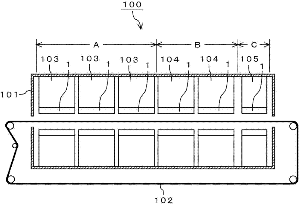
[0051] figure 1 It is a front sectional view showing a configuration example of the reflow soldering apparatus 100 according to the first embodiment. Such as figure 1 As shown, the reflow soldering apparatus 100 is composed of a main body 101 and a conveyor belt 102 for transporting a heating object such as a printed circuit board.
[0052] There are three zones of a preliminary heating zone A, a main heating zone B, and a cooling zone C in the main body portion 101 . The printed circuit boards to be soldered in the reflow soldering apparatus 100 are conveyed by the conveyor belt 102 in the order of the preliminary heating zone A, the main heating zone B and the cooling zone C.
[0053] The preliminary heating area A is an area for gradually heating the printed circuit board, electronic components mounted on the printed circuit board, etc. to adapt the printed circuit board, electronic components mounted on ...
no. 2 Embodiment approach
[0106] In this embodiment, 1 A of nozzle apparatuses which changed the shape of the suction port 3b of the nozzle apparatus 1 demonstrated in said 1st Embodiment are demonstrated. Since members having the same names and reference numerals as those in the first embodiment described above have the same functions, description thereof will be omitted.
[0107] Figure 14 It is a perspective view which shows the structural example of 1 A of nozzle apparatuses of 2nd Embodiment. Such as Figure 14 As shown, the nozzle device 1A is composed of a blowing nozzle 2 and a nozzle cover 3A. The blowing nozzle 2 is the same as the blowing nozzle described in the above-mentioned first embodiment.
[0108] The hole 3a for blowing nozzles and the suction port 3c are perforated in 3 A of nozzle covers. The suction port 3c has a circular shape, and it is pierced in the vicinity of the hole 3a for blowing nozzles so that it may be located in the vicinity of the blowing nozzle 2. Then, the su...
no. 3 Embodiment approach
[0114] In this embodiment, the blowing nozzle which changed the shape of the blowing nozzle 2 demonstrated in the said 1st Embodiment is demonstrated. Since members having the same names and reference numerals as those in the first embodiment described above have the same functions, description thereof will be omitted.
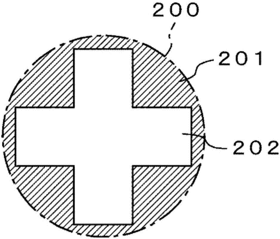
[0115] Figure 15 It is a sectional perspective view which shows the structural example of the blowing nozzle 2B of 3rd Embodiment. Such as Figure 15 As shown, the blowing nozzle 2B is composed of a nozzle main body 21B and a cross hole member 23B.
[0116] The nozzle main body 21B is different from the above-mentioned nozzle main body 21 in which the cross hole is integrally formed, and the nozzle main body 21B is formed by fitting the cross hole member 23B at the tip of the cylindrical gas flow path 24B. The nozzle main body 21B is formed of a metal material having good thermal conductivity such as aluminum or copper, and the gas flow path 24B may be for...
PUM
 Abstract
Description
Claims
Application Information
 - R&D
- Intellectual Property
- Life Sciences
- Materials
- Tech Scout
- Unparalleled Data Quality
- Higher Quality Content
- 60% Fewer Hallucinations
Browse by: Latest US Patents, China's latest patents, Technical Efficacy Thesaurus, Application Domain, Technology Topic, Popular Technical Reports.
© 2025 PatSnap. All rights reserved.Legal|Privacy policy|Modern Slavery Act Transparency Statement|Sitemap|About US| Contact US: help@patsnap.com