
Robot automatic surfacing and visual inspection system of track gear discs

A visual inspection, automatic surfacing technology, applied in welding equipment, auxiliary welding equipment, welding/cutting auxiliary equipment, etc., can solve the problems of high labor cost, low equipment utilization rate, high work intensity, etc., to optimize process parameters and The effect of high consistency of path, welding quality and high degree of equipment automation

Active Publication Date: 2017-06-20
ZHEJIANG UNIV
View PDF5 Cites 13 Cited by
  • Summary
  • Abstract
  • Description
  • Claims
  • Application Information

AI Technical Summary

Problems solved by technology

[0004] It can be seen that the current gear plate tooth profile welding method still has the following defects: 1. For the manual welding method, the welding quality of the workpiece is unstable, which is greatly affected by human factors, and the working environment of the workers is harsh and the work intensity is high; 2. For welding based Although the automatic surfacing welding method of the workstation has achieved a certain degree of automation, manual loading and unloading is still required, the utilization rate of equipment is low, and the quality of product surfacing welding has improved to a certain extent, but grinding is still required; 3. The quality of the final product depends on manual grinding Skills are greatly affected by human factors, while the working environment of the grinding process is harsh, recruitment is difficult and labor costs are high

Method used


Image

  • Robot automatic surfacing and visual inspection system of track gear discs
  • Robot automatic surfacing and visual inspection system of track gear discs
  • Robot automatic surfacing and visual inspection system of track gear discs

Examples


Embodiment Construction

[0030] The present invention will be further described below in conjunction with drawings and embodiments.

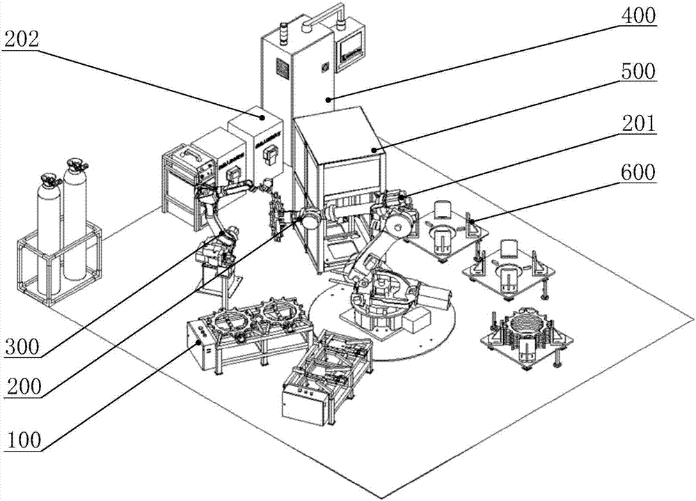
[0031] as attached figure 1 As shown, a system specifically implemented in the present invention includes two fixed silos 100 , a handling robot system 200 , a welding robot system 300 , an intelligent control system 400 , a visual inspection system 500 and two mobile silos 600 . The handling robot system 200 is set in the central area of ​​the ground, and the fixed silo 100, the welding robot system 300, the intelligent control system 400, the visual inspection system 500 and the mobile hopper 600 are all placed around the handling robot system 200; the fixed silo 100 is set in The loading station, the welding robot system 300 is placed at the welding station, the visual inspection system 500 is arranged at the inspection station, the mobile bin 600 is arranged at the unloading station, and the intelligent control system 400 is connected with the welding robot system 3...


PUM


Abstract

The invention discloses a robot automatic surfacing and visual inspection system of track gear discs. The robot automatic surfacing and visual inspection system comprises fixed material bins, a transfer robot system, a welding robot system, an intelligent control system, a visual inspection system and moving material bins. The fixed material bins are arranged at feeding stations. The welding robot system is put at a welding station. The visual inspection system is arranged at an inspection station. The moving material bins are arranged at discharging stations. The fixed material bins are used for feeding. The transfer robot system is used for firstly transferring the track gear discs to the welding robot system from the fixed material bins to be welded, then transferring the track gear discs to the visual inspection system to be subjected to welding quality inspection and finally transferring the track gear discs to the moving material bins. According to the robot automatic surfacing and visual inspection system, the functions of automatic feeding of the track gear discs, double robot cooperative welding, welding quality online inspection, finished product separating stacking and the like are achieved; the equipment automation degree is high; manual intervention is not needed in the whole process; and the welding quality consistency is high.

Description

technical field [0001] The invention relates to an automatic surfacing and quality inspection system, in particular to an automatic surfacing and visual inspection system for a crawler gear disc robot, which is a fully automatic robot integrated equipment for automatic welding processing and post-welding quality inspection of gear discs. Background technique [0002] The track gear disc is a key part of large tracked engineering vehicles, and is generally used as the driving wheel of the tracked walking system. The processing quality (machining accuracy, wear resistance) of the track gear directly affects the motion performance of the vehicle. In order to improve the wear resistance of the gear disc, it is usually necessary to surfacing a layer of wear-resistant metal material on the meshing part of the tooth shape. [0003] At present, the enterprise mainly adopts the gas metal shielded welding process to carry out surfacing welding on the tooth surface of the gear plate. ...

Claims


Application Information

Patent Timeline
IPC IPC(8): B23K37/00B23K37/02B23K37/04
CPCB23K37/00B23K37/02B23K37/04
Inventor 王郑拓徐月同卢江马景涛
Owner ZHEJIANG UNIV
Learn More