
Method for testing ferromagnetic resonance linewidth in-plane distribution of magnetic material and system thereof

A technology of ferromagnetic resonance lines and magnetic materials, which is used in magnetic resonance measurement, material analysis through resonance, and material analysis. , Improve the signal-to-noise ratio, return the effect of signal enhancement

Inactive Publication Date: 2017-06-20
UNIV OF ELECTRONIC SCI & TECH OF CHINA
View PDF5 Cites 11 Cited by
  • Summary
  • Abstract
  • Description
  • Claims
  • Application Information

AI Technical Summary

Problems solved by technology

[0003] At present, with the in-depth study of spintronics, many new technologies using local ferromagnetic resonance to detect magnetic materials have emerged, such as the micro-focus Brillouin scattering spectrum invented by Perzlmaier, the time-resolved scanning gram Scientists use real part space images of these new technologies to reflect the distribution of FMR spatial strength of magnetic materials, but these optical detection methods are limited by light diffraction, that is, limited by size (0.5 μm)
The microwave probe is used to detect the local ferromagnetic resonance of magnetic materials and then study the FMR spatial intensity distribution. Since the microwave probe has the characteristic that the detection size is only related to the radius of the probe tip, that is, if the size of the tip is small enough, it can be However, if the magnetic thin film sample is too thin, the microwave magnetic field formed by the tip of the probe in the magnetic material is very weak, which leads to a weak return signal detected and a low signal-to-noise ratio. This weak signal cannot be detected

Method used


Image

  • Method for testing ferromagnetic resonance linewidth in-plane distribution of magnetic material and system thereof
  • Method for testing ferromagnetic resonance linewidth in-plane distribution of magnetic material and system thereof
  • Method for testing ferromagnetic resonance linewidth in-plane distribution of magnetic material and system thereof

Examples


Embodiment

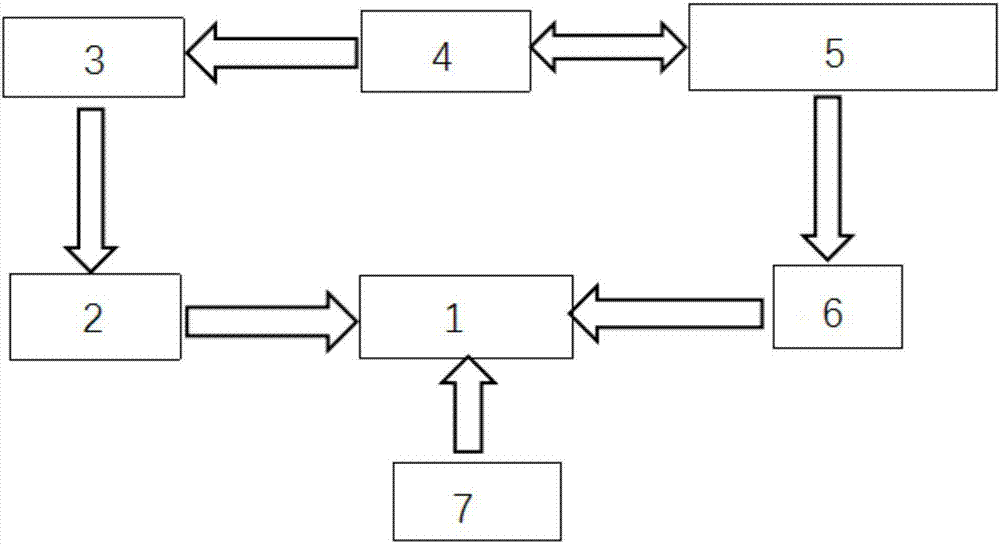
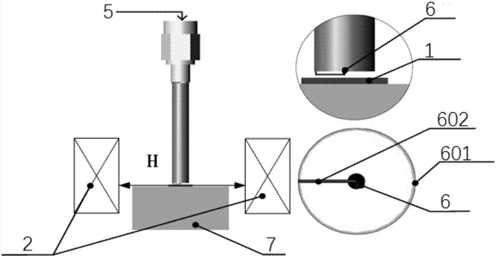
[0020] Such as figure 1 Shown is a schematic diagram of the system structure for testing magnetic material ferromagnetic resonance linewidth distribution in the present invention, including: electromagnet 2, current source 3, computer 4, vector network analysis 5, microwave probe 6 and translation stage 7; among them: The computer 4 is connected to the vector network analyzer 5 for data collection. The vector network analyzer 5 is connected to the microwave probe 6 through the radio frequency connector port, and the microwave probe 6 is set directly above the sample area on the translation stage 7, combining figure 2 It can be seen that the tip of the microwave probe 6 is connected with the outer conductor 601 of the microwave probe 6 through a gold wire 602 to form a terminal short-circuit structure, and the vector network analyzer 5 generates a microwave magnetic field parallel to the sample surface (the magnetic field intensity is expressed as h), One port of the current sour...


PUM


Abstract

The invention discloses a method for testing ferromagnetic resonance linewidth in-plane distribution of magnetic material and a system thereof, and relates to the technical field of magnetic material parameter testing. The disadvantages in the prior art that a microwave magnetic field formed by a microwave probe tip in magnetic material testing is weak can be overcome. The microwave magnetic field formed by the microwave probe tip in the magnetic material is enhanced and a vector network analyzer is enabled to acquire a stronger return signal so as to be used for testing the ferromagnetic resonance linewidth of a thinner magnetic film. The uniformity of the magnetic film can be further reflected by analyzing the difference of the ferromagnetic resonance linewidth of each area of the magnetic film sample so that the method has the advantages of being rapid and simple and convenient in comparison with the conventional optical test method.

Description

Technical field [0001] The invention relates to the technical field of magnetic material parameter testing, in particular to a method and system for testing the in-plane distribution of magnetic material ferromagnetic resonance line width. Background technique [0002] In recent years, ferromagnetic resonance, like paramagnetic resonance and nuclear magnetic resonance, has gradually developed into an important method for studying the macroscopic phenomenon and microscopic mechanism of magnetic materials. Magnetic materials are subjected to a microwave magnetic field of a certain frequency and a constant magnetic field perpendicular to the microwave magnetic field. When the frequency of the microwave magnetic field is consistent with the frequency of the magnetization precession of the magnetic material under the constant magnetic field, the magnetic material will absorb the largest amount from the microwave magnetic field. Energy, that is, resonant absorption occurs, this phenome...

Claims


Application Information

Patent Timeline
IPC IPC(8): G01R33/20
Inventor 彭斌李白雪张文旭张万里
Owner UNIV OF ELECTRONIC SCI & TECH OF CHINA
Learn More