Sulfur tail gas purification process for direct discharge after treatment

A treatment process and process technology, applied in the field of sulfur tail gas treatment process, to achieve significant desulfurization effect, ensure absorption effect, and reduce steam consumption

Active Publication Date: 2017-06-23
HEBEI REFINING TECH CO LTD
View PDF2 Cites 12 Cited by
  • Summary
  • Abstract
  • Description
  • Claims
  • Application Information

AI Technical Summary

Problems solved by technology

Such a strict index poses new challenges t

Method used


Image

  • Sulfur tail gas purification process for direct discharge after treatment
  • Sulfur tail gas purification process for direct discharge after treatment
  • Sulfur tail gas purification process for direct discharge after treatment

Examples


Embodiment 1

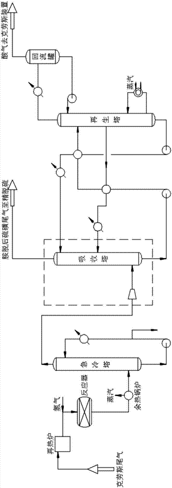
[0037] A sulfur tail gas treatment process that can be directly discharged after treatment, aimed at removing CO from raw gas with amines 2 When the content is not higher than 10% (mol / mol), based on the existing Super-SCOT process, the process is as follows figure 1 As shown, wherein: a compressor is installed between the quenching tower and the absorption tower, and the tail gas after exiting the quenching tower is pressurized to 0.15MPa by the compressor and then enters the lower part of the absorption tower. Contact for amine removal, the number of absorption stages in the absorption tower is 22 actual trays; the tail gas after amine removal is discharged from the top of the absorption tower and sent to the fine desulfurization system; the rich liquid after amine removal is discharged from the bottom of the absorption tower and sent to the upper part of the regeneration tower to be Stripping to semi-lean liquid; part of the semi-lean liquid is extracted from the 1-3 layers...

Embodiment 2

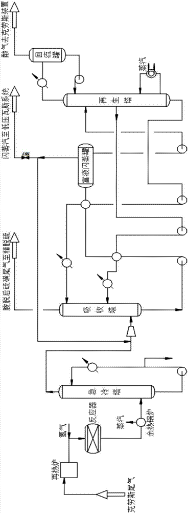
[0042] A sulfur tail gas treatment process that can be directly discharged after treatment, aimed at removing CO from raw gas with amines 2 The content is higher than 10% (mol / mol), based on the existing Super-SCOT process, the process is as follows figure 2 As shown, wherein: a compressor is set between the quenching tower and the absorption tower, and a rich liquid flash tank is set between the absorption tower and the regeneration tower; the tail gas after the quenching tower is pressurized to 0.15Mpa by the compressor and then enters the absorption tower In the lower part, the desulfurization solvent is reversely contacted with the desulfurization solvent in the absorption tower under pressurized state to carry out deamination, and the number of absorption stages in the absorption tower is 20 actual trays; the exhaust gas after deamination is discharged from the top of the absorption tower and sent to the fine desulfurization system; The rich liquid after amine removal is...

Embodiment 3

[0046] A sulfur tail gas treatment process that can be directly discharged after treatment, for sulfur tail gas with a COS content higher than 50ppm (mol / mol), based on the existing Super-SCOT process, the process is as follows figure 1 As shown, wherein: a compressor is installed between the quenching tower and the absorption tower, and the tail gas after leaving the quenching tower is pressurized to 0.20MPa by the compressor and then enters the lower part of the absorption tower. Contact for amine removal, the number of absorption stages in the absorption tower is 25 actual trays; the tail gas after amine removal is discharged from the top of the absorption tower and sent to the fine desulfurization system; the rich liquid after amine removal from the bottom of the absorption tower is sent to the upper part of the regeneration tower to be Stripping to semi-lean liquid; part of the semi-lean liquid is extracted from the 1-3 layers above the middle layer of the regeneration tow...


PUM


Abstract

The invention provides a sulfur tail gas purification process for direct discharge after treatment. On the basis of a conventional Super-SCOT process, the absorption pressure inside an absorbing tower is 0.05-0.25MPa; the absorption grade inside the absorbing tower is not smaller than that of an actual tower plate of 18 layers; a desulfuration solvent for deamination comprises the following components in percentage by weight: 20-50% of N-methyldiethanolamine (MDEA), 0-30% of diisopropanolamine (DIPA), 10-50% of sulfolane, 1-2% of a protonation agent and the balance of water; a semi lean solution is sucked out from 1-5 layers above a middle layer in the middle of a regeneration tower and is moved upwards along with increase of the content of CO2 in a deamination raw material gas; two semi lean solution inlets are longitudinally formed in the middle of the absorbing tower; when the content of the CO2 in the deamination raw material gas is higher than 10% (mol/mol), the semi lean solution is fed into the feeding hole above, or else the semi lean solution is fed into a feeding hole below; COS is hydrolyzed into H2S and CO2 by using a fine desulfurization process, H2S is adsorbed and reacts to generate sulfide, and a treated purified gas can be directly discharged. The purified gas treated by using the method can be directly discharged without incineration, and thus relatively low sulfur discharge standards can be met with relatively low energy consumption.

Description

technical field [0001] The invention relates to a sulfur tail gas treatment process, in particular to a sulfur tail gas treatment process that can be directly discharged after treatment. Background technique [0002] The Claus process is one of the methods for recovering sulfur from acid gas, and it is still the main process of acid gas treatment so far. This process is mainly used in acid gas processing units in the natural gas and petroleum refining industries, commonly known as sulfur units. After the 1960s, as developed countries gradually strengthened the monitoring of SO in sulfur tail gas 2 Emission limits require total sulfur recovery to be increased to 99.8%. In order to solve this problem, the sulfur tail gas treatment process came into being. [0003] The reduction tail gas treatment process is to convert various forms of sulfur in the tail gas into H 2 S, and then process the H through different pathways 2 S. A typical representative of this type of process...

Claims


Application Information

Patent Timeline
IPC IPC(8): B01D53/86B01D53/48
Inventor 郝天臻白春动
Owner HEBEI REFINING TECH CO LTD
Why Eureka
Try Eureka