Frequency selective surface structure with improved angle stability

A frequency selective surface, stability technology, applied in electrical components, circuits, antennas, etc., can solve the problem of not meeting the needs of resonant frequency stability, achieve good resonant stability, reduce resonant frequency offset, and increase the current path. Effect

Inactive Publication Date: 2017-06-23
XIDIAN UNIV
View PDF4 Cites 19 Cited by
  • Summary
  • Abstract
  • Description
  • Claims
  • Application Information

AI Technical Summary

Problems solved by technology

For example, in the article Zhao Z, Shi H, Guo J, et al.A Stop-band Frequency Selective Surface with Ultra-large Angle of Incidence[J].2016:1-1, the author designed a frequency selection through fractal technology On the surface, the frequency selection surface says that the resonant frequency is stable within the range of incident angles from 0° to 80°, but it cannot meet the requirements for stable resonant frequency at larger incident angles such as 85°

Method used


Image

  • Frequency selective surface structure with improved angle stability
  • Frequency selective surface structure with improved angle stability
  • Frequency selective surface structure with improved angle stability

Examples


Embodiment 1

[0025] Example 1, a frequency selective surface unit with a dielectric substrate having a relative permittivity of 2.2, a patch length of 7.5 mm, and a zigzag strip width of 0.4 mm.

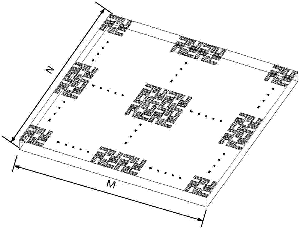
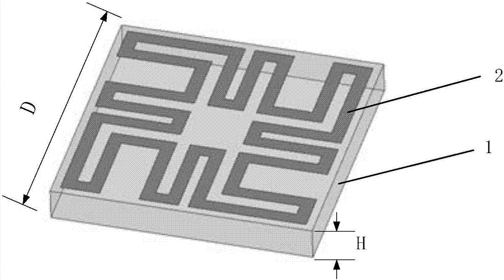
[0026] refer to figure 2 Each frequency selective surface unit in this example includes a dielectric substrate 1 and a metal patch 2 printed on its surface, and the metal patch 2 coincides with the geometric center of the upper surface of the dielectric substrate 1 . The dielectric substrate 1 adopts a square plate, and the use of the square plate ensures the polarization stability of the formed frequency selective surface structure; the side length of the dielectric substrate 1 is D=8mm, the thickness H=1mm, and the relative permittivity is 2.2.

[0027] refer to image 3 , the length and width of the metal patch 2 of each frequency selective surface unit are equal, and smaller than the side length of the dielectric substrate. In this example, the length and width of the metal patch 2 are both...

Embodiment 2

[0028] Embodiment 2, a frequency selective surface unit with a dielectric substrate having a relative permittivity of 2.25, a patch length of 8.5 mm, and a meander strip width of 0.3 mm.

[0029] The structure of this embodiment is the same as that of Embodiment 1, and only the following parameters are adjusted:

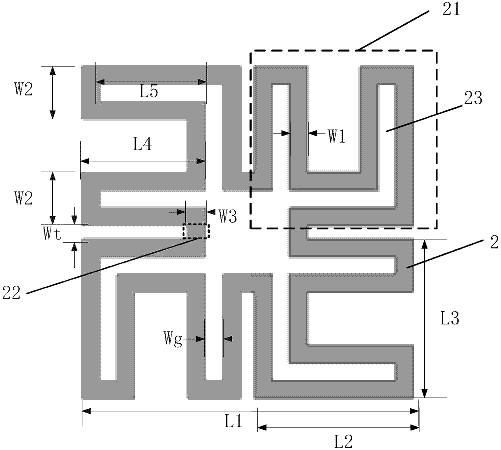
[0030] The side length of the dielectric substrate 1 is D=9mm, the thickness is H=1.5mm, and the relative dielectric constant is 2.25. The length and width of the metal patch 2 are equal, and both are L1=8.5mm; each "concave" figure 21 The length L2 and the width L3 are equal, both are 4.0mm, the width W2 of the two outer vertical arms of each "concave" figure is 1.4mm, and the length L4 is 3.0mm; the length L5 of the hollow gap 23 is 2.6mm, and the width Wg is 0.8mm; the length Wt of the rectangular strip 22 is 0.5mm, and the width W3 of the rectangular strip 22 is equal to the width W1 of the meandering strip, which is 0.3mm.

Embodiment 3

[0031] Embodiment 3, a frequency selective surface unit with a dielectric substrate having a relative permittivity of 2.65, a patch length of 9 mm, and a meander strip width of 0.5 mm.

[0032] The present embodiment has the same structure as Embodiment 1, and its parameters are as follows:

[0033] The side length of the dielectric substrate 1 is D=9.5mm, the thickness is H=2mm, the relative permittivity is 2.65, the length and width of the metal patch 2 are equal, both are L1=9mm; each "concave" figure 21 The length L2 is equal to the width L3, which are both 4.1mm. The width W2 of the two outer vertical arms of each "concave" figure is 1.6mm, and the length L4 is 3.1mm; the length L5 of the hollow gap 23 is 2.8mm, and the width Wg is 1 mm; the length Wt of the rectangular strip 22 is 0.1 mm, and the width W3 of the rectangular strip 22 is equal to the width W1 of the meandering strip, which is 0.5 mm.

[0034] Effect of the present invention can be further illustrated by f...


PUM


Abstract

The invention provides a frequency selective surface structure with improved angle stability, and mainly aims to solve the problem that the existing frequency selective surface is of poor angle stability. The frequency selective surface structure is composed of M*N frequency selective surface units arranged periodically, wherein M>=3, and N>=3. Each frequency selective surface unit consists of a dielectric substrate (1) and a metal patch (2) printed on the surface of the dielectric substrate (1). The frequency selective surface structure is characterized in that each metal patch (2) includes four symmetrically-arranged patterns (21) shaped like a Chinese character 'au'; for each pattern (21) shaped like a Chinese character 'au', the two outer vertical arms are each provided with a hollowed-out gap (23) in the middle and the lower left end is opened in such a way that a continuous winding strip is formed; and the four winding strips are connected end to end through rectangular strips (22) to form a complete square closed-loop strip. The frequency selective surface structure has high angle stability for differently-polarized incident waves, and can be used in satellite communication, reflector antennas and other fields.

Description

technical field [0001] The invention belongs to the field of microwave technology, and relates to a frequency selective surface with high angular stability, which can be used in the fields of satellite communication, reflector antenna, indoor shielding and the like. Background technique [0002] Frequency selective surface FSS is a single-layer or multi-layer planar structure composed of a large number of identical units arranged in two-dimensional periodicity. FSS itself does not absorb energy, but it can function as a filter, essentially a spatial filter. There are usually two types of FSS units on the frequency selective surface, namely the patch type and the aperture type. When the frequency of the incident wave is equal to the resonant frequency of the frequency selective surface, the two types of units show total reflection or total transmission respectively. Due to its unique filtering characteristics, frequency selective surface FSS is often used in aircraft radomes...

Claims


Application Information

Patent Timeline
Patent Type & Authority Applications(China)
IPC IPC(8): H01Q15/00H01P1/20
CPCH01Q15/0026H01P1/20
Inventor 洪涛邢文博赵强谷越龚书喜姜文刘英
Owner XIDIAN UNIV
Why Eureka
Try Eureka