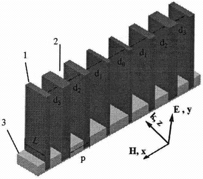
Terahertz lens based on metal plates
A terahertz lens and metal plate technology, applied in the field of terahertz lenses, can solve problems such as difficult control of precision and dangerous operation, and achieve the effects of small dispersion, easy manufacture, and simple structure
- Summary
- Abstract
- Description
- Claims
- Application Information
AI Technical Summary
Problems solved by technology
Method used
Image

Examples
Embodiment 1
[0029] Design a working wavelength as λ d = 1 mm, Φ 0 =1.66π, lens example with focal length f=10mm, period p=1mm, composed of eighteen metal plates, with seventeen metal plate gaps, according to the propagation constant formula and the phase distribution formula, the d corresponding to the phase is calculated value, as shown in Table 1 below.
[0030] Table 1
[0031] d 0
[0032] Arrange the metal plates in parallel according to the corresponding relationship in Table 1, resulting in Figure 4 The electric field strength distribution shown. Figure 4 The xz section electric field distribution diagram obtained when the focal length of the terahertz lens is designed for embodiment 1 of the present invention is f=10mm, it can be seen from the figure that the electromagnetic wave propagates through the terahertz lens based on the metal flat plate in this embodiment (the port is at z= 0.5mm) and began to converge, and at z = 10.5mm can be observed obvious focusing...
Embodiment 2
[0034] In another specific embodiment of the present invention, design a working wavelength as λ d = 1 mm, Φ 0 =1.66π, lens example with focal length f=15mm, period p=1mm, composed of twenty-eight metal plates, with twenty-seven metal plate gaps, calculated by the propagation constant formula and the phase distribution formula corresponding to the phase The value of d is shown in Table 2 below.
[0035] Table 2
[0036] d 0
d 1
d 2
d 3
d 4
d 5
d 6
d 7
d 8
d 9
d 10
d 11
d 12
d 13
x(mm) 0 ±1 ±2 ±3 ±4 ±5 ±6 ±7 ±8 ±9 ±10 ±11 ±12 ±13 Φ(π) 1.66 1.56 1.39 1.07 0.61 0.04 1.35 0.55 1.66 0.67 1.6 0.46 1.24 0 d(mm) 0.9 0.82 0.695 0.59 0.525 0.5 0.677 0.52 1.66 0.531 0.83 0.514 0.637 0.5
[0037] Arrange the metal plates in parallel according to the corresponding relationship in Table 2, resulting in Figure 6 The electric field strength distribution shown. F...
PUM
 Abstract
Description
Claims
Application Information