
Portable rechargeable microsecond pulse power supply

A microsecond pulse and rechargeable technology, which is applied in the direction of battery circuit devices, circuits, collectors, etc., can solve the problems that the working frequency cannot be unloaded for a long time, and it is not easy to carry, and achieves the effect of simple structure, low cost, and portability

Active Publication Date: 2017-06-27
NANJING UNIV OF TECH
View PDF6 Cites 7 Cited by
  • Summary
  • Abstract
  • Description
  • Claims
  • Application Information

AI Technical Summary

Problems solved by technology

[0005] The present invention proposes a portable rechargeable microsecond pulse power supply. Its purpose is to solve the problem that the existing microsecond pulse power supply needs to be connected to the mains or an external high-voltage DC power supply as power input, which is not easy to carry and cannot be used for a long time when the operating frequency is high To solve the problems of time and no load, design a miniaturized portable microsecond pulse power supply that does not need to be plugged in. It is powered by a rechargeable lithium battery pack. It has a simple and compact structure, small size, low cost, and is portable. Mains power; the pulse transformer is equipped with a demagnetization winding and an air gap, which makes the power supply suitable for no-load operation, suitable for occasions where it is difficult to obtain stable power supply, and used to drive small Power Low Temperature Plasma Reactor

Method used


Image

  • Portable rechargeable microsecond pulse power supply
  • Portable rechargeable microsecond pulse power supply
  • Portable rechargeable microsecond pulse power supply

Examples


Embodiment 1

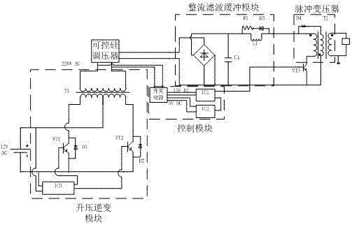
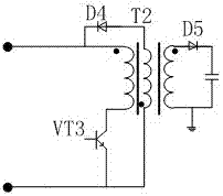
[0029] One embodiment of the invention includes the following figure 1 The lithium battery pack 101 shown, the DC boost inverter module 102, the thyristor voltage regulation module 103, the rectification filter module 104, the pulse transformer 105, the high voltage microsecond pulse output 106, the PWM signal generator 107, and the IGBT driver board 108 with IGBT109. The above modules or components are as attached figure 2 The wiring diagram shown connects the various modules and installs them in the power box. The output end of the lithium battery pack 101 is connected to the DC boost inverter module 102, the output end of the current boost inverter module 102 is connected to the thyristor voltage regulating module 103, and the output end of the thyristor voltage regulating module 103 is connected to the rectification filter module 104, the rectification and filtering module 104 is connected to the pulse transformer 105, and the end of the pulse transformer 105 is provide...


PUM


Abstract

The invention relates to a portable rechargeable microsecond pulse power supply. The structure includes a lithium battery pack, a direct current boosting inverter module, a silicon controlled voltage regulation module, a rectification and filtering module, a pulse transformer, a high voltage microsecond pulse output, a PWM signal generator, an IGBT driver board and an IGBT; the lithium battery is connected with the input end of the direct current boosting inverter module, the output end of the direct current boosting inverter module is connected with the input end of the silicon controlled voltage regulation module, the silicon controlled voltage regulation module is connected with the input end of the rectification and filtering module, the output end of the rectification and filtering module is connected with the first input end of the pulse transformer, and the tail end of the pulse transformer is provided with the high voltage microsecond pulse output; and the output end of the PWM signal generator is connected with the input end of the IGBT driver board, the IGBT driver board is connected with the input end of the IGBT, and the output end of the IGBT is connected with the second input end of the pulse transformer. The advantages are as follows: (1) the portable rechargeable microsecond pulse power supply does not need to be electrified when used, is small in volume and convenient to carry; (2) the power supply can realize long-time no-load operation; and (3) the power supply adopts modular design, is simple in structure and is low in cost.

Description

technical field [0001] The invention relates to a portable rechargeable microsecond pulse power supply, belonging to the technical field of energy conversion and storage. Background technique [0002] Low-temperature plasma has a wide range of applications and unique advantages in the fields of environmental pollution control, medical sterilization, material modification and flow control. Atmospheric pressure low-temperature plasma has the advantages of low environmental requirements, easy control, environmental protection and no pollution, and has attracted people's attention. [0003] The power sources used to generate low-temperature plasma mainly include industrial frequency AC power, high-frequency power, and pulse power. Compared with industrial frequency AC power, the atmospheric pressure low-temperature plasma generated by pulse and high-frequency power has many advantages, such as easier to generate uniform large-area plasma, better treatment effect and higher prod...

Claims


Application Information

Patent Timeline
IPC IPC(8): H02J7/00H02M7/537H02M1/32H02M3/335H01F30/06H01F27/30H01F27/32
CPCH02J7/0063H02M1/32H02M3/33523H02M7/537H01F27/306H01F27/323H01F27/324H01F30/06
Inventor 方志周若瑜史曜炜张波
Owner NANJING UNIV OF TECH
Learn More