Liquid drop flow power generation device and manufacturing method thereof
A power generation device and droplet technology, which is applied in the direction of generators, generators/motors, and electrical components that convert kinetic energy into electrical energy, can solve problems such as the controllability of liquid flow directions, and improve the utilization rate of power generation areas and overall power generation efficiency effect
- Summary
- Abstract
- Description
- Claims
- Application Information
AI Technical Summary
Problems solved by technology
Method used
Image
Examples
Embodiment 1
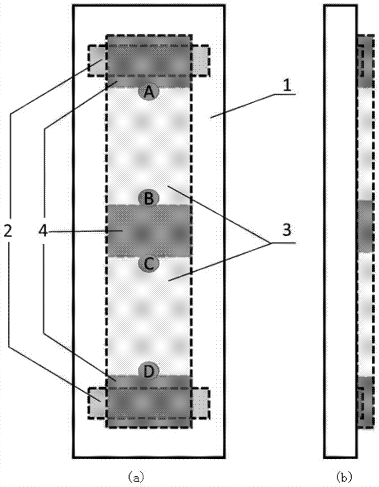
[0052] Embodiment 1 provides a droplet flow power generation device, its plan view and cross-sectional view are as follows figure 1 As shown, it includes an insulating carrier 1, an electrode 2, a flow power generation layer 3 and a hydrophobic modification layer 4; wherein, figure 1 (a) is a plan view, figure 1 (b) is a sectional view; its preparation method is as follows:
[0053] (1) Two parallel carbon nanotube electrodes 2 are printed on the insulating carrier 1 by printing;
[0054] (2) The slurry containing the carbon nanoparticle material is evenly printed on the carrier sheet and forms a continuous slurry layer across the two electrodes; the slurry is composed of a carbon nanoparticle material, a binder, and And the solvent is uniformly mixed by grinding or stirring;
[0055] (3) Annealing the printed paste layer at 300-400°C; after the annealing is completed, a porous flow power generation layer 3 composed of carbon nanoparticles is formed, and the porous flow pow...
Embodiment 2
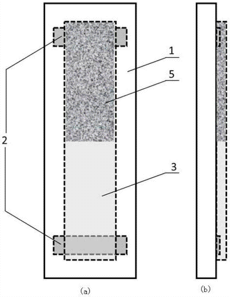
[0060] The plan view and cross-sectional view of a droplet flow power generation device provided in Embodiment 2 are as follows figure 2 as shown, figure 2 (a) is a plan view, figure 2 (b) is a cross-sectional view; including a carrier sheet 1, an electrode 2, a flow power generation layer 3 and a surface modification layer 5.
[0061] Its preparation method is as follows:
[0062] (1) Deposit two mutually parallel metal aluminum electrodes 2 on the insulating carrier 1 by means of vapor deposition;
[0063] (2) Brush the slurry containing carbon nanoparticle material on the insulating carrier 1 and form a continuous slurry layer across two electrodes 2; wherein the slurry is composed of carbon nanoparticle material with a mass ratio of 1.5:1:10 , Adhesive and solvent are uniformly mixed by grinding or stirring;
[0064] (3) Annealing the printed slurry layer at 350°C to 450°C; after annealing, a porous flow power generation layer 3 composed of carbon nanoparticles is f...
Embodiment 3
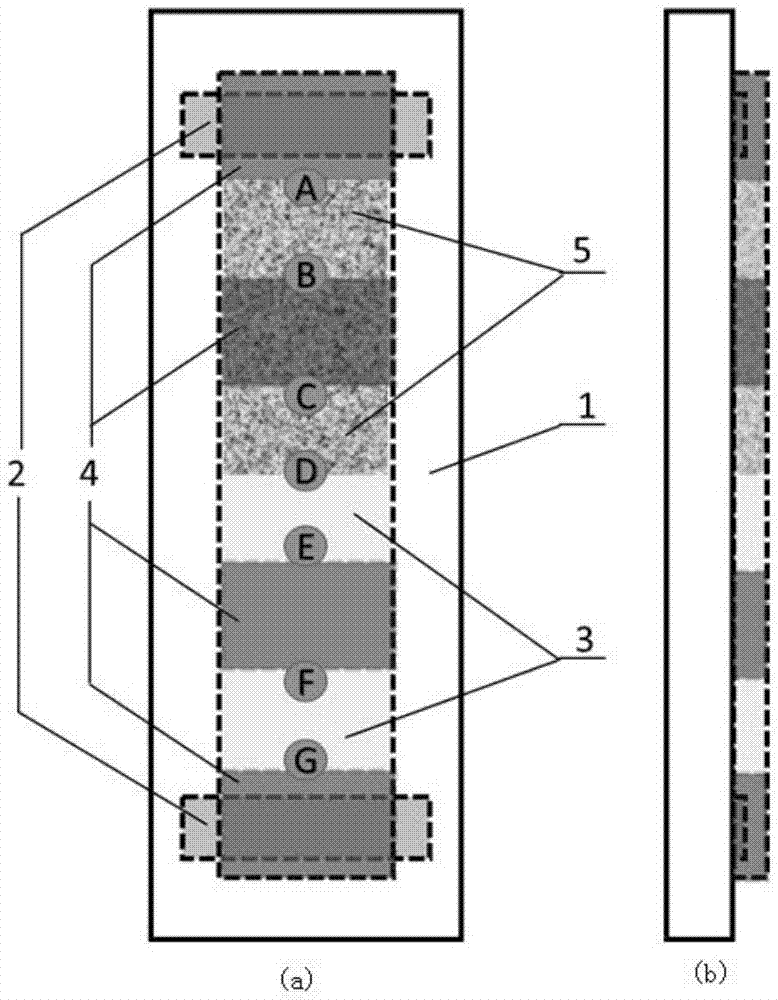
[0069] The plan view and cross-sectional view of a droplet flow power generation device provided in Embodiment 3 are as follows image 3 as shown, image 3 (a) is a plan view, image 3 (b) is a cross-sectional view; including a slide 1, an electrode 2, a flow power generation layer 3, a hydrophobic layer 4 and a surface potential modification layer 5.
[0070] Its preparation method is as follows:
[0071] (1) Print two mutually parallel carbon nanotube electrodes 2 on the insulating carrier 1;
[0072] (2) Brush the slurry containing carbon nanoparticle material on the insulating carrier to form a continuous layer across two electrodes; wherein, the slurry is composed of carbon nanoparticle material, binder and The solvent is uniformly mixed by grinding or stirring;
[0073] (3) Annealing the printed slurry layer at 350°C to 450°C. After the annealing is completed, a porous flow power generation layer 3 composed of carbon nanoparticles is formed, and the porous flow power...
PUM
 Abstract
Description
Claims
Application Information
 - R&D
- Intellectual Property
- Life Sciences
- Materials
- Tech Scout
- Unparalleled Data Quality
- Higher Quality Content
- 60% Fewer Hallucinations
Browse by: Latest US Patents, China's latest patents, Technical Efficacy Thesaurus, Application Domain, Technology Topic, Popular Technical Reports.
© 2025 PatSnap. All rights reserved.Legal|Privacy policy|Modern Slavery Act Transparency Statement|Sitemap|About US| Contact US: help@patsnap.com


