U-shaped wood-plastic canal lining and manufacturing method thereof

A manufacturing method and wood-plastic technology, applied in irrigation pipelines, applications, buildings, etc., can solve the problems of increasing the water conveyance roughness of the channel, the water content of the channel structure is large, and the water conveying capacity is reduced, and achieves good anti-seepage effect and waterproof. The effect of good anti-seepage performance and extended service life

Inactive Publication Date: 2017-07-07
NORTHEAST FORESTRY UNIVERSITY
View PDF5 Cites 1 Cited by
  • Summary
  • Abstract
  • Description
  • Claims
  • Application Information

AI Technical Summary

Problems solved by technology

In the case that the drainage cannot be cleared in autumn, the residual water in the ch...

Method used


Image

  • U-shaped wood-plastic canal lining and manufacturing method thereof
  • U-shaped wood-plastic canal lining and manufacturing method thereof
  • U-shaped wood-plastic canal lining and manufacturing method thereof

Examples


specific Embodiment approach 1

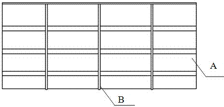
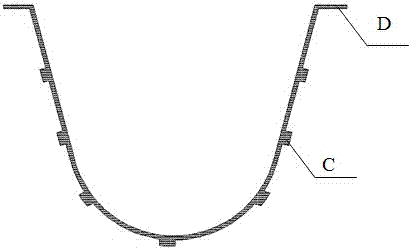
[0023] Specific implementation mode one: as figure 1 and figure 2 As shown, what is described in this embodiment is a U-shaped wood-plastic channel lining. The U-shaped wood-plastic channel lining is formed by connecting a plurality of U-shaped groove shell-shaped units A in sequence, and each U-shaped groove shell-shaped unit A The outer surface of the body A is uniformly provided with a plurality of annular reinforcing ribs B along the horizontal direction, and the outer surface of each U-shaped groove shell-shaped monomer A is uniformly provided with a plurality of long strip-shaped reinforcing ribs C along the longitudinal direction, and the U-shaped wood-plastic channel lining The two ends of the top are respectively provided with lugs D along the longitudinal direction, and the plurality of annular reinforcing ribs B, the plurality of elongated reinforcing ribs C, the two lugs D and the plurality of U-shaped groove shell-shaped monomers A are integrated (It is processe...

specific Embodiment approach 2

[0024] Specific implementation mode two: as figure 1 As shown, the U-shaped wood-plastic channel lining described in Embodiment 1, the wall thickness of the U-shaped wood-plastic channel lining is 6-12mm, and the length of each U-shaped groove shell-shaped monomer A is 1~1.5m, the height of each U-shaped groove shell-shaped monomer A is 400~600mm, and the diameter of the inner bottom surface circle of each U-shaped groove shell-shaped monomer A is 250~350mm.

specific Embodiment approach 3

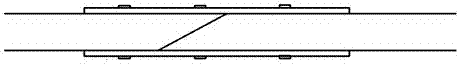
[0025] Specific implementation mode three: as image 3 As shown, in the U-shaped wood-plastic channel lining described in Embodiment 1 or 2, every two adjacent U-shaped groove shell-shaped monomers A are connected by a half-lap joint of cuts.

[0026] Specific implementation mode four: as image 3 As shown, in the U-shaped wood-plastic channel lining described in Embodiment 3, the incisions between two adjacent U-shaped groove shell-shaped monomers A are connected by glue joints and semi-lap joints (firstly Use sandpaper to polish the cut surface of the joint, and apply a silane coupling agent solution to increase the bonding strength of the wood-plastic composite surface. After standing for 20-30 minutes, apply the adhesive evenly on the joint to achieve cementation and half-lap connection).

[0027] Specific implementation mode five: as image 3 As shown, for a U-shaped wood-plastic channel lining described in Embodiment 4, the bonding width of the inner and outer surface...


PUM


Abstract

The invention discloses a U-shaped wood-plastic canal lining and a manufacturing method thereof and belongs to the technical field of hydraulic engineering. The U-shaped wood-plastic canal lining is composed of stiffeners, U-shaped pot-shell-shaped single bodies and anchorage plate. The manufacturing method of the U-shaped wood-plastic canal lining comprises the following steps that (1), a cellulase modifier water solution is sprayed on a wood fiber powder material and talcum powder, and then drying is conducted; (2), the wood fiber powder material and the talcum powder are mixed; (3), polyolefin plastics, polyolefin elastomers (POE), an anti-ultraviolet agent and a compatilizer are mixed, and particle manufacturing is conducted; (4), a mixture of the step (2) is mixed with a particle material of the step (3), and a plasticized particle material is extruded out; and (5), the plasticized particle material is extruded or injected, and the U-shaped wood-plastic canal lining is manufactured. Compared with the prior art, the U-shaped wood-plastic canal lining has the advantages that the service life is long, the water conveying capacity is improved, the water-proof and leakage-proof properties are good, the anti-corrosion and anti-aging properties are good, the structure is simple, dismounting, mounting and conveying are convenient, and the environment-friendly effect is achieved.

Description

technical field [0001] The invention belongs to the technical field of water conservancy engineering, and in particular relates to a U-shaped wood-plastic channel lining and a manufacturing method thereof. Background technique [0002] In agricultural irrigation and drainage projects, artificial channel linings such as concrete, stone masonry, and brick masonry are generally used. These channels are easily corroded and deformed by the water vapor and moisture in the soil, which reduces the strength of the channels and causes leakage of the channel walls, resulting in waste and pollution of water resources. In addition, the construction of these channel linings takes a long time, the cost of labor and daily maintenance is high, and it is not easy to install and disassemble. [0003] At present, the main failure types of concrete, stone and brick channel linings are freeze-thaw failures in winter and spring. In the case that the drainage cannot be cleared in autumn, the resi...

Claims


Application Information

Patent Timeline
IPC IPC(8): E02B13/00C08L23/00C08L97/02C08L23/08C08K3/34B29C45/00
CPCB29C45/0001C08L23/00C08L2205/02C08L2205/03E02B13/00C08L97/02C08L23/0815C08K3/34
Inventor 张兴丽张正刚王清文房轶群
Owner NORTHEAST FORESTRY UNIVERSITY
Why Eureka
Try Eureka