Folded thin film capacitor and fabrication method thereof

A technology of film capacitors and manufacturing methods, which is applied in the direction of film/thick film capacitors, laminated capacitors, fixed capacitor leads, etc., can solve the problem that the small contact area cannot effectively improve the contact resistance of the electrode end, which is easy to fall off, and the energy storage density of the capacitor Problems such as drop and increase of non-stacked parts can solve the problems of less contact points, reduce current density and loss, and improve service life

Active Publication Date: 2017-07-07
SOUTHWEST JIAOTONG UNIV
View PDF6 Cites 12 Cited by
  • Summary
  • Abstract
  • Description
  • Claims
  • Application Information

AI Technical Summary

Problems solved by technology

However, this process is complex and costly, and the small contact area cannot effectively improve the contact resistance at the end of the electrode, which is easy to fall off when the dista

Method used


Image

  • Folded thin film capacitor and fabrication method thereof
  • Folded thin film capacitor and fabrication method thereof
  • Folded thin film capacitor and fabrication method thereof

Examples


Embodiment Construction

[0028] 下面结合附图对本发明的具体技术方案作进一步地描述。

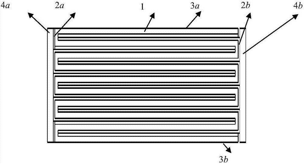
[0029] Such as Figure 3-4 所示,本发明的一种折叠薄膜电容器,薄膜电容器具有多层金属化薄膜相互折叠而成的层叠体,且金属化薄膜的有机薄膜和金属蒸镀膜为交替层叠的方式,需要说明的是,本发明的薄膜折叠薄膜电容器中的金属化薄膜的折叠层数不受附图的任何限制。

[0030] 通过折叠在薄膜电容器的两个侧面以整面的方式存在金属蒸镀膜,通过在侧面的金属蒸镀膜上喷镀金属粒子而形成喷金层4a和4b,喷金层可靠地与侧面的金属蒸镀膜连接在一起。上述两个喷金层的构成材料没有特别限制,可将锌、铝等一直以来常规使用的物质作为两个喷金层的构成材料使用。需要说明的是,根据需要,在上述喷金层上可分别连接图上未给出的端子等。

[0031] 金属化薄膜包括有机薄膜1和在有机薄膜1的表明蒸镀金属后形成的金属蒸镀膜2a和2b,有机薄膜为聚丙烯、聚苯硫醚、聚酯、聚苯乙烯或聚碳酸酯,有机薄膜1的两侧边缘设有未蒸镀金属蒸镀膜的空白留边3a和3b。金属化薄膜的有机薄膜1和金属蒸镀膜的各自厚度没有特别限制,但通常有机薄膜1的厚度为1μm~25μm,金属蒸镀膜的厚度在0.3nm~30nm左右。

[0032] 需要说明的是,为了使本发明的薄膜折叠薄膜电容器的结构容易理解,分别以夸大的尺寸表示出了金属化薄膜的有机薄膜1及金属蒸镀膜、喷金层的厚度,同时还以极少于实际数目的数目例示了薄膜电容器中金属化薄膜的折叠层数。

[0033] 为增加喷金层和金属蒸镀膜之间的附着,可在折叠时将相邻电极层之间进行错边,即相互相邻的金属化膜以使其中的一个金属化膜端部从另一个 金属化膜的端部突出的方式相互叠合,由此同一电极中相邻两个金属化膜形成缝隙,从而使喷镀金属粒子可侵入到缝隙内,与缝隙及突出部分的金属蒸镀膜紧密 connect.

[0034] 本发明的折叠薄膜电容器的制作方法是,包括以下步骤:

[0035]1) Taking material and trimming: Use a film cutter to cut the metallized film raw material into the required width of the capacitor. The metallized fi...


PUM


Abstract

The invention provides a folded thin film capacitor and a fabrication method thereof. The folded thin film capacitor comprises a metal thin, two metal spraying layers (4a and 4b), two electrode terminals and a shell, wherein the two electrode terminals are respectively connected with the two metal spraying layers (4a and 4b), the folded thin film capacitor is characterized in that the metal film comprises a first metal evaporation film (2a), a second metal evaporation film (2b) and an electrical insulation polymer basic layer (1), the electrical insulation polymer basic layer (1) is sandwiched between the two metal evaporation films (2a and 2b), the metal film is repeatedly folded to form a cuboid block in a longitudinal direction, folded angles of the first metal evaporation film (2a) and the second metal evaporation film (2b) are superposed to respectively form a first side surface and a second side surface of the block, and the two metal spraying layers (4a and 4b) are respectively arranged on the first side surface and the second side surface. By the folded thin film capacitor and the fabrication method thereof, the problem that a metal spraying electrode at an end part of the thin film capacitor is seldom in contact with a metal film contact point is solved, heat generation of the end part of the capacitor is reduced, the internal inductance and the internal resistance of the capacitor are reduced, the lifetime of the capacitor is prolonged, and the folded thin film capacitor is particularly suitable for the field of large-current application.

Description

technical field [0001] 本发明属于电子元器件技术领域,具体涉及一种折叠薄膜电容器及制作方法。 Background technique [0002] 一直以来,在各种电子设备、电气设备、电磁发射装置中使用电容器,近年来,为了应对电子设备、电气设备、电磁发射装置的小型化的要求,逐渐大量地使用金属化薄膜电容器作为上述电容器。金属化膜电容器的特点在于采用蒸镀方法将金属膜附着在绝缘介质上,因此金属膜的厚度通常在10nm左右,对应的金属膜方阻约为毫欧。由于金属膜的厚度远小于绝缘薄膜的厚度,因此可以实现高储能密度;同时金属膜的厚度足够小使得电弱点击穿时产生的能量能够将附近的金属气化,从而再次实现击穿点的电绝缘,只是损失了微小的电容器容量及能量。但正是金属膜厚度小的特点限制了金属膜的应用范围,特别是在大电流应用需求领域。能量损耗与电流的平方成正比关系,因此电流过大时将产生较大的热量,由于金属膜厚度相对于薄膜厚度要小几个量级,因此金属薄膜电容器的等效热导率与薄膜(0.2W / m.℃)自身的热导率相当,这就使得金属膜的温度上升明显。 [0003] 目前,金属化膜电容器的制作方法主要采用两种:一是将薄膜卷绕在绝缘芯上;另一种则是采用多层叠片形式,如 figure 1 所示,可以看出第一极性膜和第二极性膜有多片,与隔离膜从分离状态下叠加在一起的。这两种方法均存在同样的缺陷,即在制作金属化薄膜电容器的电极时,现有技术是对第一极性膜2a’、第二极性膜2b’和隔离膜1’叠加的端部采用喷金形式,使喷涂金属4’与二种极性的金属膜2a’、2b’连接,喷涂粒子的典型尺寸与相邻层之间的金属膜厚相当甚至更大,这就使得喷涂粒子很难与金属膜之间完全紧密接触,更多的是点接触形式,如 figure 2 shown. 这就使得接触点电流密度大、损耗大、发热严重,在电、热、机械应力的共同作用下,使得电极终端很容易出现脱落现象。 [0004] 现有技术中在制作金属化膜电容器时,为解决电容器端部在大电流应用场合的缺陷问题,也有采用在金属膜边缘采用加厚镀膜,从而使边缘的电阻减小为原来的3~4分之一,同时增加喷镀粒子与金属膜的接触面积,但改善效果并不理想。另外也有在相邻电极层之间进行错边,即相互相邻的金属化膜以使其中的一个金属化膜端部从另一个金属化膜的端部突出的方式...

Claims


Application Information

Patent Timeline
IPC IPC(8): H01G4/33H01G4/228H01G4/232
CPCH01G4/228H01G4/232H01G4/33
Inventor 王庆峰刘庆想张健穹李相强张政权
Owner SOUTHWEST JIAOTONG UNIV
Why Eureka
Try Eureka