Electric power-assisted braking system used for automobile

A technology of electric power assist and braking system, applied in the direction of brakes, brake transmission devices, vehicle components, etc., can solve the problems of large space occupied by the braking system, long braking response time, insufficient braking force, etc., and achieve rapid action response. , low cost and sufficient braking force

Active Publication Date: 2017-07-11
SUN YAT SEN UNIV +1
View PDF6 Cites 10 Cited by
  • Summary
  • Abstract
  • Description
  • Claims
  • Application Information

AI Technical Summary

Problems solved by technology

[0002] In the process of technological development of electric vehicles, active safety technology plays a decisive role and is an important guarantee for vehicle safety. Among them, the braking system of vehicle wheels is particularly important; the boosting system for traditional vehicle braking is provided by the fuel engine intake manifold. Negative pressure, the air pressure is converted into mechanical force through a vacuum booster (commonly known as a big drum). Since electric vehicles do not have a fuel engine, the power-assisted braking system does not have a vacuum source to rely on. The current method used is to attach an electric vacuum pump to the electric vehicle. Negative pressure devices such as vacuum tanks and pressure valves convert electricity into air pressure, and then convert the air pressure into mechanical force through a large drum, and then act on the piston of the brake master cylinder. However, this method has long braking response time, Low reliability, high noise and other disadvantages. At the same time, multiple negative pressure devices also make the entire braking system occupy a particularly large space, and the braking force generated during continuous braking is insufficient.

Method used


Image

  • Electric power-assisted braking system used for automobile
  • Electric power-assisted braking system used for automobile
  • Electric power-assisted braking system used for automobile

Examples


Embodiment Construction

[0041] In order to facilitate the understanding of those skilled in the art, the present invention will be further described below in conjunction with the embodiments and accompanying drawings, and the contents mentioned in the implementation modes are not intended to limit the present invention.

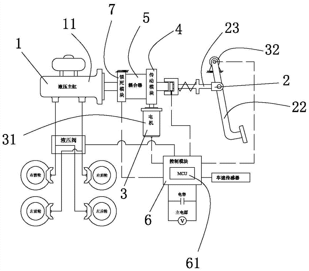
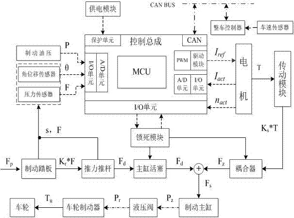
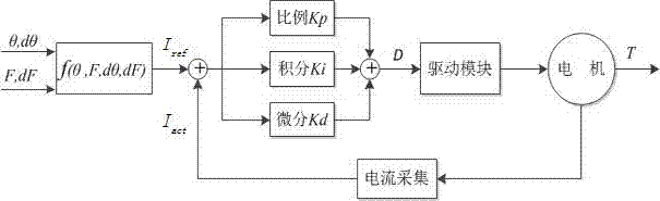
[0042] see Figure 1 to Figure 3, an electric power-assisted braking system for automobiles of the present invention includes a braking force output hydraulic module 1, a braking force input mechanical module 2, an electric power-assisted input module 3 and a control assembly 6, and the electric power-assisted input module 3 includes a transmission module 4. Coupler 5 and sensor 32, the braking force input mechanical module 2 directly acts on the braking force output hydraulic module 1 through the coupler 5, the sensor 32 is installed on the braking force input mechanical module 2, and the motor 31 is sequentially coupled through the transmission module 4, The device 5 acts on the b...


PUM


Abstract

The invention relates to the technical field of automobile braking and particularly discloses an electric power-assisted braking system used for an automobile. The electric power-assisted braking system comprises a braking force output hydraulic module, a braking force input mechanical module, an electric power-assisted input module and a control assembly. The electric power-assisted input module comprises a motor, a transmission module and a sensor. The braking force input mechanical module directly acts on the braking force output hydraulic module through a coupler. The motor is connected with the coupler through the transmission module. The control assembly is used for setting a control strategy and is in electrical signal connection with the motor and the sensor. According to the electric power-assisted braking system used for the automobile, the modular design is adopted, the braking response time is shortened, the braking reliability and the braking efficiency are improved, and the occupied space is reduced; the braking system is provided with a protection unit with redundant measures and has a driver pedal force braking way and a motor braking way, and a traditional operation mode by a driver is retained; and the control mode can be adjusted, man-machine interaction can be conducted, a plurality of driving styles are provided, and the electric power-assisted braking system can meet the braking requirements of automatic driving and can further be matched with a regenerative braking system to achieve braking together.

Description

technical field [0001] The invention relates to the technical field of automobile braking, and in particular discloses an electric power-assisted braking system for automobiles. Background technique [0002] In the process of technological development of electric vehicles, active safety technology plays a decisive role and is an important guarantee for vehicle safety. Among them, the braking system of vehicle wheels is particularly important; the boosting system for traditional vehicle braking is provided by the fuel engine intake manifold. Negative pressure, the air pressure is converted into mechanical force through a vacuum booster (commonly known as a big drum). Since electric vehicles do not have a fuel engine, the power-assisted braking system does not have a vacuum source to rely on. The current method used is to attach an electric vacuum pump to the electric vehicle. Negative pressure devices such as vacuum tanks and pressure valves convert electricity into air press...

Claims


Application Information

Patent Timeline
Patent Type & Authority Applications(China)
IPC IPC(8): B60T13/74
CPCB60T13/745
Inventor 熊会元邓威宗志坚陈冰锋
Owner SUN YAT SEN UNIV
Why Eureka
Try Eureka