Fiber laser sensor light-carried microwave signal digital demodulation system and demodulation method thereof

A light-borne microwave and fiber laser technology, which is applied in the direction of using optical devices to transmit sensing components, etc., can solve the problem of insufficient demodulation capability of large dynamic broadband light-borne microwave signals, limited frequency response bandwidth of radio frequency analog circuits, and difficulty in dynamically providing signals Frequency, amplitude and other issues, to achieve the effect of easy adjustment, fast speed and high demodulation accuracy

Active Publication Date: 2017-07-11
CHINA ELECTRONIC TECH GRP CORP NO 38 RES INST
View PDF5 Cites 14 Cited by
  • Summary
  • Abstract
  • Description
  • Claims
  • Application Information

AI Technical Summary

Problems solved by technology

Conventional spectrum analysis technology can only obtain the frequency offset, and it is difficult to dynamically provide information such as frequency and amplitude of the signal, so a special demodulation method is required
In addition, the traditional fiber laser sensor demodulation system mostly adopts analog mode, the system is easily affected by device aging, temperature drift, etc., the frequency response bandwidth of the RF analog circuit is limited, and the demodulation capability for large dynamic broadband light-borne microwave signals is insufficient

Method used


Image

  • Fiber laser sensor light-carried microwave signal digital demodulation system and demodulation method thereof
  • Fiber laser sensor light-carried microwave signal digital demodulation system and demodulation method thereof
  • Fiber laser sensor light-carried microwave signal digital demodulation system and demodulation method thereof

Examples


Embodiment Construction

[0029] In order to make the object, technical solution and advantages of the present invention clearer, the present invention will be further described in detail below in conjunction with the accompanying drawings and embodiments. It should be understood that the specific embodiments described here are only used to explain the present invention, not to limit the present invention.
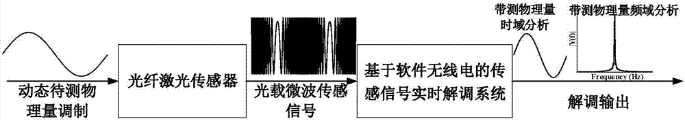
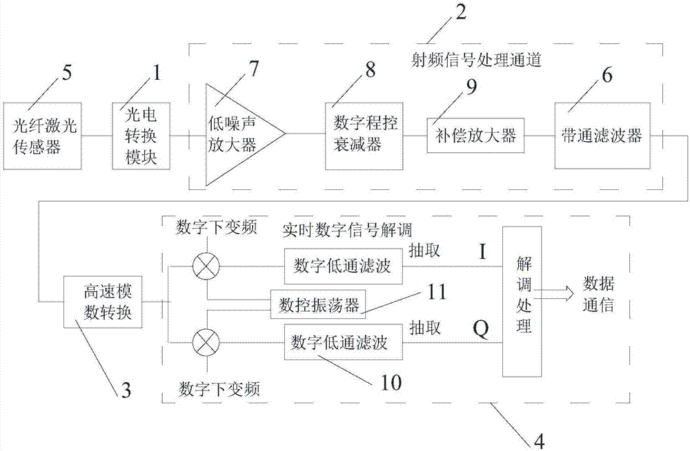
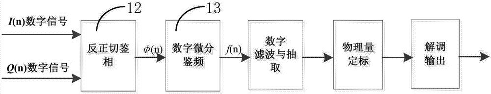
[0030] Based on the idea of ​​software radio, the present invention uses a high-speed analog-to-digital converter to directly collect the optical-carrying microwave signal (that is, the optical-carrying microwave broadband large dynamic sensing signal) output by the fiber laser sensor, and uses a general-purpose and standardized digital signal processing platform to process the signal in real time. By demodulating sensing signals, the system reduces the burden of complex RF analog circuit design, and the system architecture is simple. The main functions of the system are realized by software, which...


PUM


Abstract

The invention discloses a fiber laser sensor light-carried microwave signal digital demodulation system and the demodulation method thereof. The system is used to demodulate the light-carried microwave signal outputted from a fiber laser sensor and outputs a demodulation signal capable of restoring a wideband large dynamic sensing signal in real time. The system comprises a photoelectric conversion module, a radio frequency signal processing channel module, a high-speed analog-to-digital conversion module, and a real-time digital signal demodulation processing module. The radio frequency signal processing channel module performs automatic gain amplification and bandpass filtering on the heterodyne frequency modulation signals outputted by the photoelectric conversion module in sequence and converted into digitalized radio frequency signals by the high-speed analog-to-digital conversion module. The real-time digital signal demodulation processing module uses two channels of orthogonal local oscillator sequences to multiply the digitalized radio frequency signals respectively, and two orthogonal baseband signals are obtained from the downsampling after the low-pass filtering followed by the division, four-direction anti-tangent operation, and then the periodic expansion of the arctangent result so that the phase demodulation phase signal obtained from phase adjustment is subjected to digital differential processing.

Description

technical field [0001] The present invention relates to a demodulation system and its demodulation method in the technical field of optical fiber sensor signal demodulation, especially to a digital demodulation system and demodulation method of optical fiber laser sensor light-borne microwave signal, which is mainly used in extreme Detection of weak dynamic signals such as vibration acceleration and underwater sound pressure in the environment. Background technique [0002] Compared with various traditional sensing technologies, optical fiber sensing has the advantages of high sensitivity, anti-electromagnetic interference, good electrical insulation, corrosion resistance, low energy consumption, safe measurement, flexible and light optical fiber, and easy networking and multiplexing. Therefore, it is widely used in many special conditions. The optical fiber sensor modulates the light transmitted in the optical fiber by the measured object, changes the intensity (amplitude)...

Claims


Application Information

Patent Timeline
Patent Type & Authority Applications(China)
IPC IPC(8): G01D5/353
CPCG01D5/353
Inventor 王凯李成强武帅李武建汪灏李季
Owner CHINA ELECTRONIC TECH GRP CORP NO 38 RES INST
Why Eureka
Try Eureka