
Composite insulator defect non-destructive detection method

A composite insulator and non-destructive testing technology, applied in the field of electric power, can solve problems such as easy missed inspection, low universality, and wrong inspection, and achieve the effect of stable judgment, clear standards, and accurate defect identification

Inactive Publication Date: 2017-07-14
STATE GRID JIANGSU ELECTRIC POWER CO LIANYUNGANG POWER SUPPLY CO +2
View PDF4 Cites 8 Cited by
  • Summary
  • Abstract
  • Description
  • Claims
  • Application Information

AI Technical Summary

Problems solved by technology

[0006] It can be seen that the existing composite insulator defect detection equipment has defects such as low universality, easy missed detection, and wrong detection.

Method used


Image

  • Composite insulator defect non-destructive detection method
  • Composite insulator defect non-destructive detection method
  • Composite insulator defect non-destructive detection method

Examples


Embodiment 1

[0045] figure 2 It is a structural schematic diagram of an embodiment of the composite insulator defect non-destructive testing device proposed by the present invention. As shown in the figure, the composite insulator defect non-destructive testing device includes a microwave source 11, a waveguide 12, a coupling probe 13, a receiver 14, a receiving machine 15 and analyzer 16.

[0046] Wherein, the microwave source 11 provides microwave signals with variable frequency, the frequency range is 4-30GHz, the step interval is 0.1MHz, and the microwave bands are divided as follows: C-band 4-8GHz, X-band 8-12GHz, Ku-band 12-18GHz , K-band 18-27GHz, Ka-band 27-40GHz. The core band used by this device to realize the defect detection function is about 20-26GHz, so it is called "near K band". In actual use, any continuous frequency sweep band can be selected within this interval;

[0047] The waveguide 12 is a transmission device for microwave frequency sweep signals, and is used for ...


PUM

PropertyMeasurementUnit
frequencyaaaaaaaaaa

Abstract

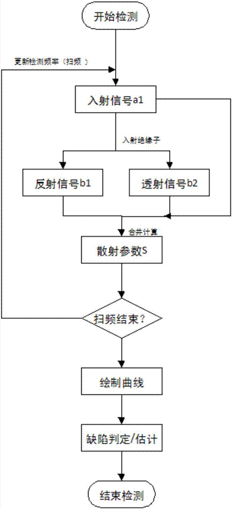
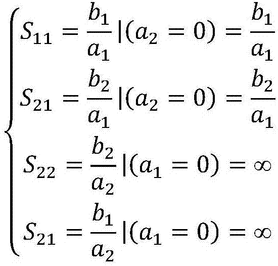
The invention discloses a composite insulator defect non-destructive detection method, which comprises that A) a frequency sweep microwave signal source is controlled to emit an incident signal, the incident signal is transmitted by a physical probe into a composite insulator, a reflection signal and a transmission signal are generated, and a receiving probe collects the three signals and sends to an analyzer to process; B) the analyzer performs combined calculation according to the amplitudes and phases of the three signals to obtain a scattering parameters S; C) a step D) is performed if one complete frequency sweep detection is completed, the frequency of the incident signal of the frequency sweep microwave signal source is adjusted if one complete frequency sweep detection is not completed, and the process returns to the step A); D) after one complete frequency sweep detection is completed, a series of scattering parameters S are obtained, and a frequency-scattering parameter S curve is drawn; and E) according to the change condition of the curve, the defect of the composite insulator to be detected is judged and estimated. With the composite insulator defect non-destructive detection method of the present invention, the state and the defect of the composite insulator can be precisely and efficiently diagnosed according to the change condition of the scattering parameters of the composite insulator.

Description

technical field [0001] The invention relates to the field of electric power technology, in particular to a defect detection method of a composite insulator. Background technique [0002] At present, the number of composite insulators in use in hanging grids in my country is about 7 million, and this number has been growing. As the cornerstone of high-voltage transmission line insulation, composite insulators play an irreplaceable role in ensuring national safety in production and life. Due to shed aging, mechanical fracture and other reasons, many defects that cannot be identified by naked eyes often appear inside or outside the composite insulator. The existence of these defects will greatly reduce the electrical performance of composite insulators, and eventually lead to major accidents such as pollution flashover. [0003] At present, the non-destructive testing of internal defects of composite insulators mainly includes ultrasonic, infrared, microwave, ultraviolet and ...

Claims


Application Information

Patent Timeline
Patent Type & Authority Applications(China)
IPC IPC(8): G01N22/02
CPCG01N22/02
Inventor 伏祥运梅红伟黄河陈洁李红高赫刘明赵晨龙朱立位王黎明
Owner STATE GRID JIANGSU ELECTRIC POWER CO LIANYUNGANG POWER SUPPLY CO
Learn More