
An infrared in-situ reaction test device based on pump detection and its application method

An in-situ reaction and testing device technology, applied in measurement devices, instruments, scientific instruments, etc., can solve the problems that it cannot be used to study the reaction of different gases and samples, and can not be filled with different gases, so as to expand the scope of application, effectively resist the Corroded, precision-manufactured effects

Active Publication Date: 2019-11-08
XI AN JIAOTONG UNIV
View PDF4 Cites 1 Cited by
  • Summary
  • Abstract
  • Description
  • Claims
  • Application Information

AI Technical Summary

Problems solved by technology

However, the existing in-situ reaction device cannot fill the in-situ reaction cell with different gases, and cannot be used to study the reaction between different gases and samples

Method used


Image

  • An infrared in-situ reaction test device based on pump detection and its application method
  • An infrared in-situ reaction test device based on pump detection and its application method
  • An infrared in-situ reaction test device based on pump detection and its application method

Examples


Embodiment 1

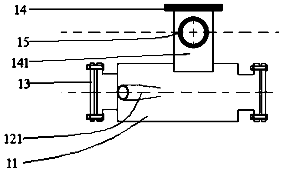
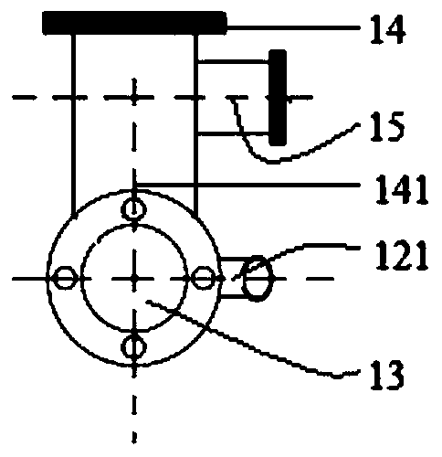
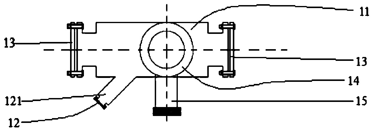
[0065] An infrared in-situ reaction test device based on pump detection, including an in-situ reaction cell, a gas buffer mixing cell, a base and a sample device, wherein, such as Picture 1-1 , Figure 1-2 and Figure 1-3 As shown, the in-situ reaction cell includes a horizontal cylindrical reaction cell casing 11, and detection windows 13 are detachably arranged at both ends of the reaction cell casing 11; The housing branch 121, the axis of the reaction pool housing 11 and the axis of the housing branch 121 form an included angle of 45°. The end of the casing branch 121 is detachably provided with the pump window 12; the reaction cell casing 11 is provided with a vertical cylindrical sample branch 141, and the sample branch 141 is hollow and its axis passes through the bottom of the reaction cell casing 11. The intersection of the axis and the axis of the housing branch 121; the end of the sample branch 141 is provided with a sample port joint 14, and the side of the sampl...

Embodiment 2

[0088] Take the study of the charge carrier dynamics of ZnO semiconductor as an example. After dispersing the ZnO powder in ethanol, add it dropwise on the calcium fluoride crystal of Φ13mm and 1mm in thickness, dry it under an infrared lamp, fix it in the sample holder 42, and adjust the nut of the sample holder 42 to ensure that the height of the sample is at At the intersection plane of the probe light and the pump light, rotate the top cover 41 angles at the same time, so that the surface of the sample is perpendicular to the pump light. Connect the CF bayonet or flange and other connecting parts, turn on the power of the mechanical pump and vacuum gauge, and vacuum overnight to remove the physical adsorption components on the surface of the sample. After the nitrogen gas is pumped into a vacuum, the pump light uses the triple frequency light (355nm) of the semiconductor laser (the fundamental frequency is 1064nm) to excite the sample, and the detection wavelength is 2000-...


PUM

PropertyMeasurementUnit
Sensitivityaaaaaaaaaa

Abstract

The invention provides an infrared in-situ reaction test device based on pumping detection. The infrared in-situ reaction test device comprises an in-situ reaction pool, a gas buffering mixing pool, a base and a sample device, wherein the in-situ reaction pool comprises a hollow reaction shell, a detection window plate, a pumping window plate, a sample hole joint and an extract opening joint; the gas buffering mixing pool comprises a hollow mixing pool shell, a bayonet joint, a needle valve and two ball valve joints, wherein the mixing pool shell is connected with the extract opening joint through a ball valve; the base is used for supporting the in-situ reaction pool; the sample device comprises a sample holder and a top cover, wherein the sample holder and the top cover are connected for bearing a sample, and therefore, the sample is positioned on an intersection of an optical path which passes through the detection window plate and the optical path which passes through the pumping window plate; the top cover is detachably connected with the sample hole joint. The test device can be assorted with an infrared spectrometer to obtain the transient spectrum of reflection, transmission and adsorption under different atmospheres and pressures. The invention also provides a use method for the test device. The method is convenient in operation.

Description

technical field [0001] The invention relates to an in-situ reaction test device based on pump detection, in particular to an infrared in-situ reaction test device based on pump detection and a use method thereof. Background technique [0002] The pump-detection technology uses pump light to excite the sample, and at the same time a beam of probe light detects the change of the sample after excitation, which is mainly used to study the charge carrier dynamics of materials that respond to light. According to the frequency and time resolution of the pump light, the dynamic characteristics of the photogenerated charge carriers at different time scales can be obtained; according to the different wavelengths of the probe light, the dynamic characteristics of the photogenerated charge carriers at different energy scales can be obtained. Current research has extended from the macroscopic scale of seconds or milliseconds to the microscopic scale of picoseconds or femtoseconds. Infra...

Claims


Application Information

Patent Timeline
Patent Type & Authority Patents(China)
IPC IPC(8): G01N21/3563
CPCG01N21/3563
Inventor 郭烈锦郭鹏慧
Owner XI AN JIAOTONG UNIV
Learn More