Device and method for treating coking wastewater by utilizing blast furnace slag

A technology for coking wastewater and blast furnace slag, which is applied in the field of iron and steel metallurgy, can solve the problems of high pollutant concentration, threaten human health, and be difficult to degrade, and achieve the effects of low content of harmful substances, saving drying costs, and improving vitrification rate.

Active Publication Date: 2017-07-21
SHANDONG IRON & STEEL CO LTD
View PDF5 Cites 3 Cited by
  • Summary
  • Abstract
  • Description
  • Claims
  • Application Information

AI Technical Summary

Problems solved by technology

The concentration of pollutants in coking wastewater is high, and polycyclic aromatic hydrocarbons in coking wastewater are not only difficult to degrade, but are usually strong carcinogens, causing serious pollution to the environment and directly threatening human health

Method used


Image

  • Device and method for treating coking wastewater by utilizing blast furnace slag
  • Device and method for treating coking wastewater by utilizing blast furnace slag

Examples


Embodiment 1

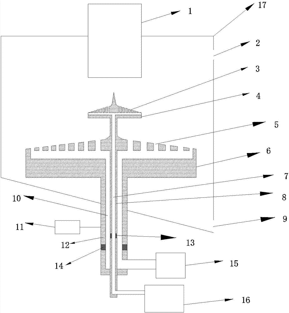
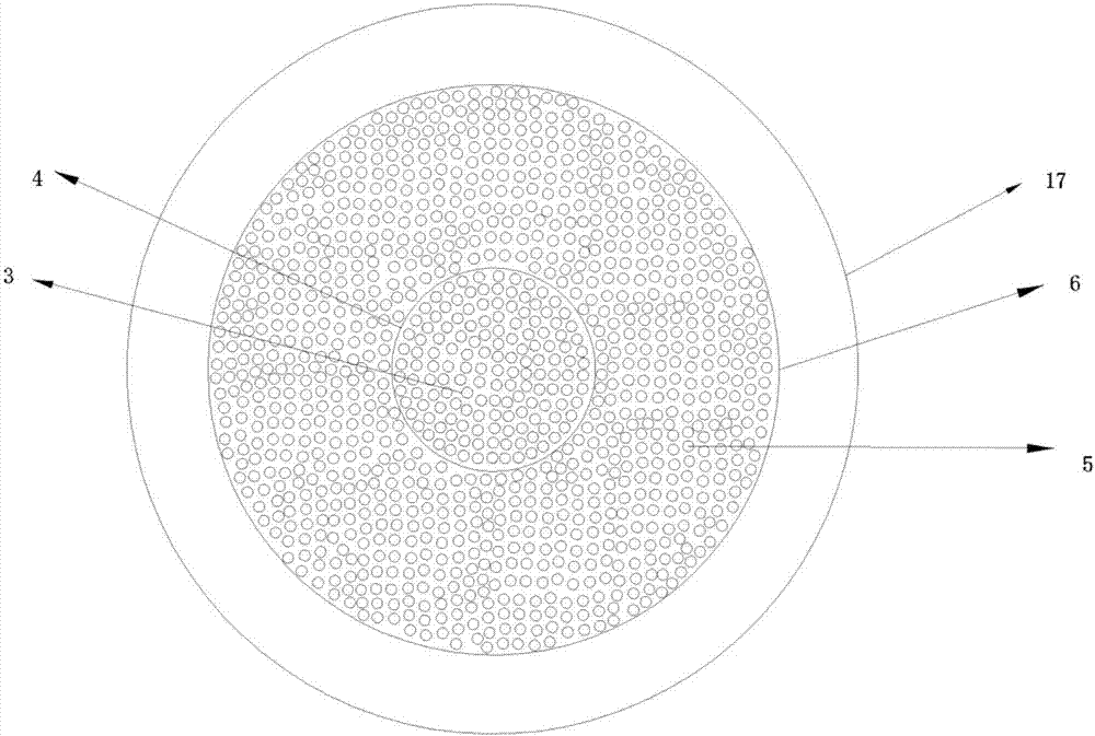
[0035] The following examples are shown together with the device figure 1 , 2 A device for treating coking wastewater with blast furnace slag is further described.

[0036] use as figure 1 , figure 2 The equipment shown in the figure performs two-step treatment of blast furnace slag. The first step is: after the blast furnace slag falls from the circular slag inlet 1, the coking waste water and blast furnace slag are used for convective spraying to cool the blast furnace slag to 700 ~1000°C, the blast furnace slag is granulated during the cooling process, and the organic matter in the coking wastewater is combusted and decomposed to generate CO 2 、H 2 O and other substances. The second step is: using the cooling air to further cool the blast furnace slag, the cooling air and the blast furnace slag convective heat transfer and convective drying, and the blast furnace slag can be further cooled, granulated and dried.

[0037] use as figure 1 , figure 2 The shown perfor...

Embodiment 2

[0041] The following examples are shown together with the device figure 1 , 2 A method for treating coking wastewater by using blast furnace slag is further explained.

[0042] use as figure 1 , figure 2 The equipment shown in the figure performs two-step treatment of blast furnace slag. The first step is: after the blast furnace slag falls from the circular slag inlet 1, the coking waste water and blast furnace slag are used for convective spraying to cool the blast furnace slag to 700 ~1000°C, the blast furnace slag is granulated during the cooling process, and the organic matter in the coking wastewater is combusted and decomposed to generate CO 2 、H 2 O and other substances. The second step is: using the cooling air to further cool the blast furnace slag, the cooling air and the blast furnace slag convective heat transfer and convective drying, and the blast furnace slag can be further cooled, granulated and dried.

[0043] use as figure 1 , figure 2 The shown pe...


PUM

PropertyMeasurementUnit
diameteraaaaaaaaaa
diameteraaaaaaaaaa

Abstract

The invention discloses a device and method for treating coking wastewater by utilizing blast furnace slag. The device comprises a first convex disc, a second convex disc, a first pipeline and a second pipeline. The first convex disc is hollow, the upper surface is provided with a plurality of coking wastewater spraying holes, the second convex disc is hollow, and the upper surface is provided with a plurality of cooling air spraying holes. The first convex disc is arranged on the second convex disc, and the first convex disc is smaller than the second convex disc in diameter. One end of the second pipeline is fixedly connected with the center of the bottom of the second convex disc, and the first pipeline penetrates through the second pipeline and the second convex disc to be fixedly connected with the center of the bottom of the first convex disc. A coking wastewater flow channel is formed in the first pipeline and is communicated with the coking wastewater spraying holes through the hollow inside of the first convex disc. A cooling air flow channel is formed between the inner surface of the second pipeline and the outer surface of the first pipeline.

Description

technical field [0001] The invention belongs to the technical field of iron and steel metallurgy, in particular, the invention relates to a device and method for treating coking wastewater by using blast furnace slag. Background technique [0002] Blast furnace slag is a high-temperature waste slag produced in the iron and steel metallurgy process. Its temperature is about 1450°C, and each ton of slag contains 260×10 sensible heat. 3 ~1880×10 3 kJ, roughly equivalent to the calorific value released when 60kg of standard coal is burned. At present, domestic and foreign blast furnace slag treatment methods are to flow the blast furnace slag into a pool for water extraction treatment, and the product is used as an admixture for cement. However, the traditional water quenching process has disadvantages such as serious consumption of water resources, large emissions of sulfur-containing gases, further dehydration and drying of the obtained slag, and basically no recovery of res...

Claims


Application Information

Patent Timeline
Patent Type & Authority Applications(China)
IPC IPC(8): C02F1/00C21B3/08F23G7/04C02F101/30C02F103/34
CPCF23G7/04C21B3/08C02F1/00C02F2101/30C02F2103/34
Inventor 刘洪银郝帅孙建卫杨波王孝科路峰袁鹏举亓伟伟王奉县
Owner SHANDONG IRON & STEEL CO LTD
Why Eureka
Try Eureka