Three-dimensional fluorescent differential super-resolution microscopic method and device

A three-dimensional fluorescence and super-resolution technology, applied in the field of optical super-resolution microscopy, can solve the problems of inability to achieve high-resolution imaging, and achieve the effects of convenient adjustment, fast imaging speed, and easy adjustment

Active Publication Date: 2017-07-21
ZHEJIANG UNIV
View PDF6 Cites 20 Cited by
  • Summary
  • Abstract
  • Description
  • Claims
  • Application Information

AI Technical Summary

Problems solved by technology

Due to the existence of the "diffraction limit", the optical microscopy imaging system

Method used


Image

  • Three-dimensional fluorescent differential super-resolution microscopic method and device
  • Three-dimensional fluorescent differential super-resolution microscopic method and device
  • Three-dimensional fluorescent differential super-resolution microscopic method and device

Examples


Embodiment Construction

[0058] The present invention will be described in detail below in conjunction with the embodiments and accompanying drawings, but the present invention is not limited thereto.

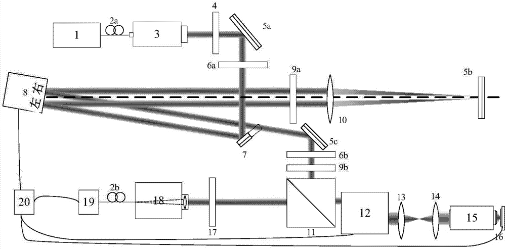
[0059] like figure 1 The three-dimensional fluorescent differential super-resolution microscope shown includes: a laser 1, a single-mode fiber 2a, a collimator 3, a polarizer 4, a mirror 5a, a 1 / 2 wave plate 6a, a D-shaped mirror 7, and spatial light modulation Device 8, 1 / 4 wave plate 9a, lens 10, reflector 5b, reflector 5c, 1 / 2 wave plate 6b, 1 / 4 wave plate 9b, four bandpass dichromatic mirrors 11, vibrating mirror scanning system 12, scanning mirror 13, field lens 14, microscope objective lens 15, sample mirror 16, four bandpass filters 17, electric pinhole 18, single-mode optical fiber 2b, detector 19, control system and PC machine 20.

[0060] Wherein, the thin optical fiber 2a, collimator 3, polarizer 4 and reflector 5a are sequentially located on the optical axis emitted by the laser 1, and the...


PUM


Abstract

The invention discloses a three-dimensional fluorescent differential super-resolution microscopic device which comprises a laser, an electric sample stage carrying a sample to be detected, and a microobjective for projecting light rays to the electric sample stage, wherein a polarizer for converting a beam emitted by the laser into linear polarized light, a first half wave plate for modulating a polarization direction of the linear polarized light, a space light modulation module for sequentially modulating a horizontal component and a vertical component of the beam and a scanning galvanometer system for light path deflection of circularly polarized light are sequentially arranged between the laser and the microobjective; the circularly polarized light emitted by the scanning galvanometer system is projected by the microobjective onto the sample to be detected; the device further comprises a detection system acquiring signal light emitted by the sample to be detected, and a computer controlling the space light modulation module and the scanning galvanometer system. The invention further discloses a microscopic method achieved on a basis of the three-dimensional fluorescent differential super-resolution microscopic device.

Description

technical field [0001] The invention belongs to the field of optical super-resolution microscopy, in particular to a three-dimensional fluorescent differential super-resolution microscopy method and device. Background technique [0002] In 1873, the German scientist Abbe proposed the "diffraction limit" of the optical imaging system. Any optical microscope has a resolution limit, which is determined by the wavelength of light and the numerical aperture of the lens. Due to the existence of the "diffraction limit", optical microscopy imaging systems cannot achieve high-resolution imaging below 200 nanometers in the visible light band. For this reason, people continue to work hard to research and develop super-resolution imaging technology, hoping to break through the diffraction limit and obtain higher resolution. In 2014, three scientists engaged in fluorescence super-resolution optical microscopy won the Nobel Prize in Chemistry. They opened the door for humans to use fluor...

Claims


Application Information

Patent Timeline
IPC IPC(8): G01N21/64
Inventor 刘旭朱大钊陈友华刘文杰匡翠方张克奇毛磊
Owner ZHEJIANG UNIV
Why Eureka
Try Eureka