Isolation circuit

A technology for isolating circuits and isolating capacitors, applied in the direction of logic circuit interface devices, logic circuit connection/interface layout, etc., can solve problems such as misoperation, instability, and high power consumption of light-emitting diodes, and achieve high isolation voltage, stable quality, and long life. long effect

Pending Publication Date: 2017-07-21
2PAI SEMICON CO LTD
View PDF3 Cites 1 Cited by
  • Summary
  • Abstract
  • Description
  • Claims
  • Application Information

AI Technical Summary

Problems solved by technology

[0003] However, the disadvantage of the optocoupler is that because the electrical properties of the light-emitting diode vary with temperature, the electrical properties of the optocoupler vary with temperature and are unstable.
In addition, because the light-emitting diode and the isolated plastic have aging problems, the optocoupler isolator also has performance aging problems
Furthermore, the optocoupler also has the problem of low common-mode re

Method used


Image

  • Isolation circuit
  • Isolation circuit
  • Isolation circuit

Examples


Embodiment Construction

[0037] Exemplary embodiments of the present disclosure will be described in more detail below with reference to the accompanying drawings. Although exemplary embodiments of the present disclosure are shown in the drawings, it should be understood that the present disclosure may be embodied in various forms and should not be limited by the embodiments set forth herein. Rather, these embodiments are provided for more thorough understanding of the present disclosure and to fully convey the scope of the present disclosure to those skilled in the art.

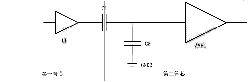
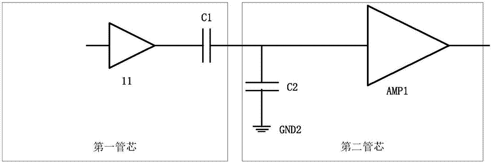
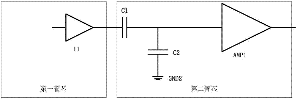
[0038] figure 1 is a circuit diagram of an isolation circuit according to an embodiment of the present invention.

[0039] Such as figure 1 As shown, the circuit diagram according to one embodiment of the present invention includes: a first buffer 11, a main isolation capacitor C1, a second capacitor C2 and a first amplifier AMP1, wherein the output of the first buffer 11 is connected to the One end of the main isolation capacitor ...


PUM


Abstract

The invention provides an isolation circuit which comprises a main isolation capacitor, a second capacitor and a first amplifier, wherein the main isolation capacitor has one end and another end, the other end of the main isolation capacitor is connected to one end of the second capacitor and the input end of the first amplifier, the other end of the second capacitor is connected to a second ground terminal, and the second capacitor and the first amplifier are in a second tube core. Through one or more embodiments of the present invention, high isolation voltage can be achieved, since the circuit and the isolation capacitor are made by CMOS process, the problems of the aging of an optocoupler, the change of performance with temperature and poor electric performance do not exist, so the quality is stable, the service life is long, and the cost is low.

Description

technical field [0001] The present invention relates to the field of circuits, and more particularly, to an isolation circuit in the field of high-voltage circuits. Background technique [0002] An optocoupler is a device that transmits signals through light as a medium. Usually, the light emitter and the receiver (photosensitive semiconductor tube) are packaged in the same package. When a current signal is applied to the input end, the light emitter emits light, and the receiver generates photocurrent after receiving the light, and outputs it from the output end, thereby realizing the "electricity-optical-electricity" conversion. The optocoupler is a photocoupler that uses light as a medium to couple the input signal to the output. The optocoupler is a technology fifty years ago. It is the first time to realize signal isolation by a device. It has been widely used in power control circuits. application. [0003] However, the disadvantage of the optocoupler is that because...

Claims


Application Information

Patent Timeline
IPC IPC(8): H03K19/0175
CPCH03K19/017509
Inventor 董志伟
Owner 2PAI SEMICON CO LTD
Why Eureka
Try Eureka