
Carbon fiber composite material, preparation method thereof, and radar antenna using the same

A composite material and radar antenna technology, which is applied in the field of radar communication, can solve the problems that the radar antenna cannot meet the application requirements of modern airport monitoring, the adverse impact on the safety of the airport scene control, and the slow scanning speed of the radar antenna, so as to ensure the high reliability of the whole machine performance, improve work reliability, and ensure the effect of fixed connection stability

Active Publication Date: 2020-01-21
ANHUI SUN CREATE ELECTRONICS
View PDF8 Cites 0 Cited by
  • Summary
  • Abstract
  • Description
  • Claims
  • Application Information

AI Technical Summary

Problems solved by technology

On the one hand, when the radar antenna that has reached the above-mentioned height above the ground is turned around with the axis of rotation as the plumb line, the situation of "darkness under the light" is often prone to occur; The larger the blind area of ​​irradiation, this obviously has an adverse effect on the control safety of the airport scene
On the other hand, the current radar antenna boxes are all made of aluminum alloy frame structure, which has a complex structure, a large number of parts, heavy weight and large size, which often affects the high-speed rotation of the radar antenna, which in turn makes the The scanning speed of the radar antenna to the observation area is reduced
With the continuous increase of air traffic, the effective management requirements of ground aircraft and motor vehicles are becoming more and more prominent, which will only increase the requirements for the technical indicators of the antenna box of the radar, such as the size, weight, and wind load area. The material of the traditional radar antenna And the structure has been difficult to meet the application requirements of modern airport monitoring

Method used


Image

  • Carbon fiber composite material, preparation method thereof, and radar antenna using the same
  • Carbon fiber composite material, preparation method thereof, and radar antenna using the same
  • Carbon fiber composite material, preparation method thereof, and radar antenna using the same

Examples


preparation example Construction

[0034]The carbon fiber composite material of the present invention is made up of epoxy resin and high-strength carbon fiber; The weight percentage of each component is calculated by 100%, and the weight percentage of high-strength carbon fiber is 60%~70%, and the weight percentage of epoxy resin is 30%-40%; wherein, the high-strength carbon fiber is a continuous filament carbon fiber treated with polyacrylonitrile. In the epoxy resin, the latent amine curing agent accounts for 5-10% of the total amount of the epoxy resin; that is, if the total amount of the epoxy resin is 100 parts, the latent amine curing agent accounts for 5-10 parts. During specific preparation, its preparation method comprises the following steps:

[0035] 1), take raw material according to above-mentioned each percentage by weight;

[0036] 2) Adopt dry molding process to obtain uniform glue-containing prepreg made of epoxy resin;

[0037] 2) Lay the prepreg and high-strength carbon fiber layer by layer...

Embodiment 1

[0041] 1), based on the weight of each component and calculated by 100%, the weight percentage of the high-strength carbon fiber is 60%, and the weight percentage of the epoxy resin is 40%; wherein, the high-strength carbon fiber is polypropylene Continuous filament carbon fiber treated with nitrile; in the epoxy resin, the latent amine curing agent accounts for 5% of the total amount of the epoxy resin. During specific preparation, its preparation method comprises the following steps:

[0042] 2) Adopt dry molding process to obtain uniform glue-containing prepreg made of epoxy resin;

[0043] 2) Lay the prepreg and high-strength carbon fiber layer by layer on the surface of the mold cavity in the form of a layer of prepreg and a layer of high-strength carbon fiber; when laying, pay attention to the different orientations of the parts. Pre-design the laying direction of the high-strength carbon fiber layer;

[0044] 3) Put the mold treated in step 2) into an oven, heat-prese...

Embodiment 2

[0046] 1), based on the weight of each component and calculated by 100%, the weight percentage of the high-strength carbon fiber is 70%, and the weight percentage of the epoxy resin is 30%; wherein, the high-strength carbon fiber is polypropylene Continuous filament carbon fiber treated with nitrile; in the epoxy resin, the latent amine curing agent accounts for 10% of the total amount of the epoxy resin. During specific preparation, its preparation method comprises the following steps:

[0047] 2) Adopt dry molding process to obtain uniform glue-containing prepreg made of epoxy resin;

[0048] 2) Lay the prepreg and high-strength carbon fiber layer by layer on the surface of the mold cavity in the form of a layer of prepreg and a layer of high-strength carbon fiber; when laying, pay attention to the different orientations of the parts. Pre-design the laying direction of the high-strength carbon fiber layer;

[0049] 3) Put the mold treated in step 2) into an oven, heat-pres...


PUM


Abstract

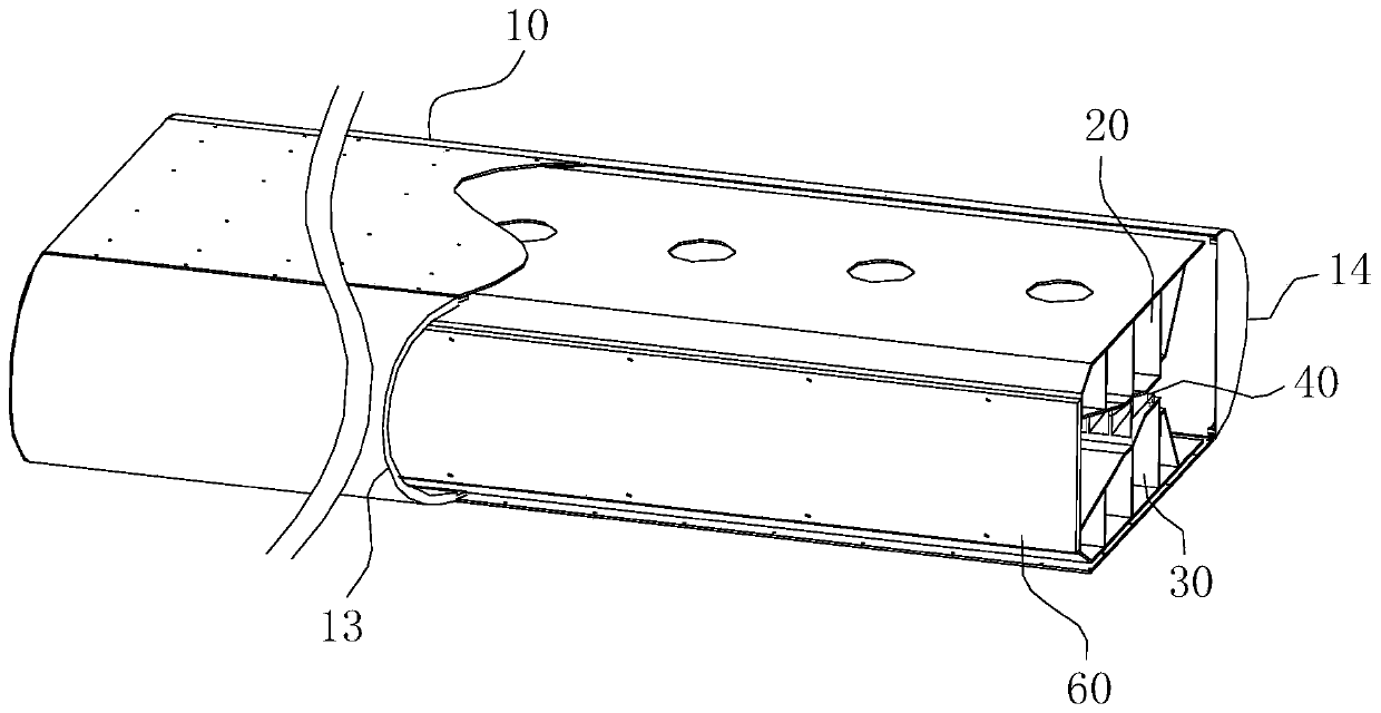
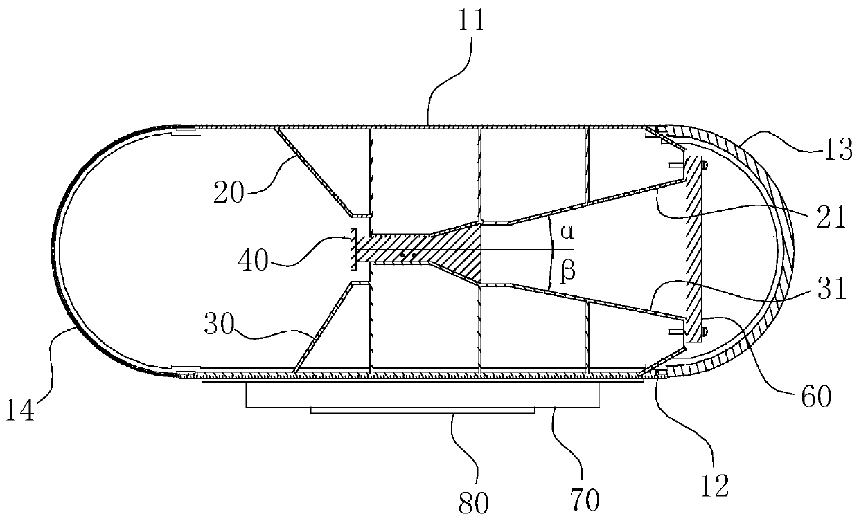
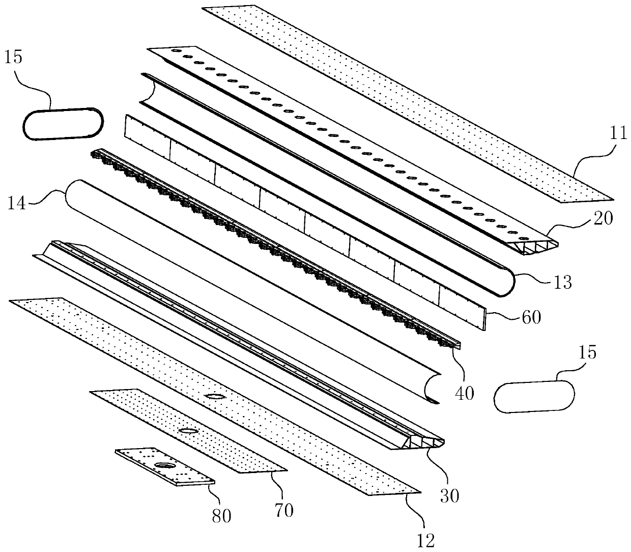
The invention belongs to the technical field of radar communication, and more specifically relates to a carbon-fibre composite as well as a preparation method thereof and a radar antenna using the carbon-fibre composite. The carbon-fibre composite comprises epoxy resin and high strength carbon fiber; the total weight of all components is 100%, the weight percentage of the high strength carbon fiber is 60-70%, and the weight percentage of epoxy resin is 30-40%; the high strength carbon fiber is continuous filament type carbon fiber treated by polyacrylonitrile; the fiber has low density, high tensile strength and yield strength. The preparation method comprises the following steps: obtaining of prepreg, layered paving as well as insulation and pressure maintaining. The radar antenna comprises a casing, a feed network, an upper frame and a lower frame, the cross sections of the upper frame and the lower frame are trapezoids with narrow top and wide bottom, and a gap between the upper frame and the top of the lower frame forms an arrangement area for clamping and fixing the feed network. The radar antenna has the advantages of light quality, maintenance convenience, short manufacture period, and low manufacture cost.

Description

technical field [0001] The invention belongs to the technical field of radar communication, and in particular relates to a carbon fiber composite material, a preparation method thereof and a radar antenna using the material. Background technique [0002] For many years, airport surface management has been influenced by a combination of ground environment and weather conditions. The airport surface surveillance radar system is an important part of air traffic management facilities. It has high real-time target detection capability and can reliably and accurately detect the movement of aircraft and motor vehicles on the airport surface. Installing surface surveillance radar equipment and surveillance equipment at appropriate locations in the airport can enable controllers to know the traffic conditions on the airport surface under any conditions, thereby greatly improving the control conditions and safety of the airport surface and improving the efficiency of ground operations...

Claims


Application Information

Patent Timeline
Patent Type & Authority Patents(China)
IPC IPC(8): B32B9/00B32B5/02B32B9/04B32B5/26B32B7/12B32B7/08B32B33/00B32B37/12B32B37/10B32B37/06H01Q1/36H01Q1/42
CPCB32B5/26B32B7/08B32B7/12B32B33/00B32B37/06B32B37/10B32B37/12B32B2037/1269B32B2250/20B32B2262/106B32B2307/50B32B2307/54H01Q1/36H01Q1/42
Inventor 李成丁飞
Owner ANHUI SUN CREATE ELECTRONICS
Learn More