Automatic sample injection system based on micro-fluidic chip

A microfluidic chip and automatic sampling technology, applied to laboratory containers, laboratory utensils, chemical instruments and methods, etc., can solve the problem of increasing system cost and operational difficulty, increasing the risk of cross-contamination, and the size of electroosmotic flow Different problems, to achieve the effect of improving the degree of detection automation, reducing the risk of cross-contamination, and improving the level of automation

Active Publication Date: 2017-07-28
北京旌准医疗科技有限公司
View PDF6 Cites 17 Cited by
  • Summary
  • Abstract
  • Description
  • Claims
  • Application Information

AI Technical Summary

Problems solved by technology

Among them, the migration speed of positive and negative ions in the electric field is inconsistent during the electrokinetic sampling process, resulting in a different concentration of the sample from the sample solution, and the change in the surface properties of the chip capillary will lead to a difference in the size of the electroosmotic flow, which greatly reduces the accuracy of the injection volume; The sample uses a syringe pump to drive the sample in the sample cell into the separation channel. In order to reduce the separation efficiency caused by the diffusion and dilution of the sample in the buffer, it is usually necessary to use multiple syringe pumps or PC-controlled solenoid valves to form a stable sample, which increases the system Cost and Difficulty of Operation
[0005] It can be seen that the microfluidic chip sampling system must rely on external pumps or different types of valve bodies to cooperate, resulting in most of the various analysis and detection instruments being in a manual and semi-automatic state.
For example, when using an ordinary microfluidic capillary electrophoresis chip for DNA fragment analysis, it is still necessary to manually add the PCR-amplified sample to the chip, which is complicated to operate, restricts the detection throughput and increases the risk of cross-contamination

Method used


Image

  • Automatic sample injection system based on micro-fluidic chip
  • Automatic sample injection system based on micro-fluidic chip
  • Automatic sample injection system based on micro-fluidic chip

Examples


Embodiment Construction

[0034] Embodiments of the present invention are described in detail below, examples of which are shown in the drawings, wherein the same or similar reference numerals designate the same or similar elements or elements having the same or similar functions throughout. The embodiments described below by referring to the figures are exemplary and are intended to explain the present invention and should not be construed as limiting the present invention.

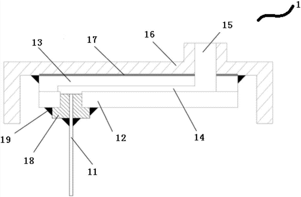
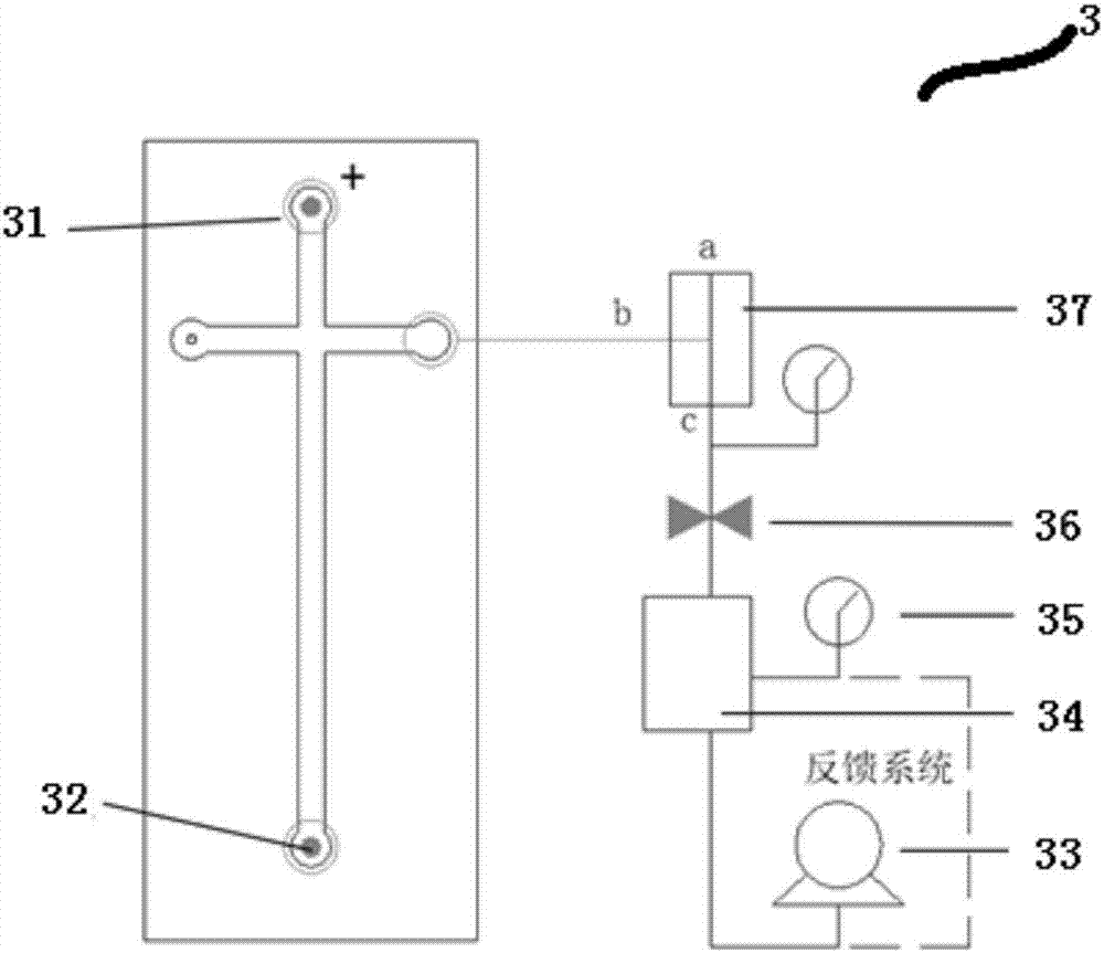
[0035] Please refer to Figure 1-Figure 3 , figure 1 It is a structural schematic diagram of a specific embodiment of the microfluidic chip in the automatic sampling system provided by the present invention; figure 2 It is a structural schematic diagram of a specific embodiment of the sampling device in the automatic sampling system provided by the present invention; image 3 It is a structural schematic diagram of a specific embodiment of the negative pressure control system in the automatic sampling system provided by the pr...


PUM


Abstract

The invention discloses an automatic sample injection system based on a micro-fluidic chip. The automatic sample injection system comprises a micro-fluidic chip and a sample injection device for inputting samples into the micro-fluidic chip, and further comprises a negative pressure control device for generating negative pressure, wherein the sample injection device comprises a porous plate for accommodating samples; a suction needle is connected to the sample injection port of the micro-fluidic chip in a sealed manner; the negative pressure control device generates air pressure from the porous plate to the micro-fluidic chip, so that the samples in the porous plate are sucked into the micro-fluidic chip through the suction needle. According to the automatic sample injection system, the samples are directly led into the micro-fluidic chip through the suction needle by virtue of the negative pressure, manual sample adding is avoided, the detection automation degree is improved, and the cross contamination risk is reduced.

Description

technical field [0001] The invention belongs to the field of biotechnology, and in particular relates to an automatic sampling system based on a microfluidic chip. Background technique [0002] Microfluidics is a technology to precisely control and manipulate micro-scale fluids. This technology originated in the 1980s, and has been rapidly developed and widely used in gene chip (DNA Microarray), point-of-care (POCT) and laboratory-on-a-chip (LOC). The microfluidic chip is also called "lab on a chip". It is the main platform for the realization of microfluidic technology. It can integrate the basic operation units such as sample preparation, reaction, separation, and detection in the process of biological, chemical, and medical analysis. The entire analysis process is automatically completed on a micron-scale chip. Microfluidic chips have the advantages of less sample consumption, fast detection speed, easy operation, multi-functional integration, small size, and portabilit...

Claims


Application Information

Patent Timeline
Patent Type & Authority Applications(China)
IPC IPC(8): B01L3/00
Inventor 姚文亮叶锋
Owner 北京旌准医疗科技有限公司
Why Eureka
Try Eureka