Tank body multi-angle polishing grinding machine

A multi-angle, polishing technology, used in grinding/polishing equipment, grinders, belt grinders, etc., can solve the problems of inconvenient operation, high cost, long processing time, etc., to reduce equipment investment, fine crystal size, Good grinding effect

Pending Publication Date: 2017-07-28
南阳龙腾专用车制造有限公司
View PDF6 Cites 16 Cited by
  • Summary
  • Abstract
  • Description
  • Claims
  • Application Information

AI Technical Summary

Problems solved by technology

[0002] At present, in the traditionally used tank or container polishing process, two equipments, the barrel polisher and the head polisher, are used to grind and polish the barrel and head of the tank or container respectively. The processing time is long and the polished After the head and the cylinder are welded, when the cylinder is polished again, the outer surface of the head will be polluted again. However, after the head and the cylinder are welded and formed, the head cannot be polished. Processing brings great inconvenience
[0003] The prior art also discloses a tank head integrated polishing machine, which is provided with two cross arms, and the two cross arms are arranged side by side on the column through the hanging board, and one end of the two cross arms is Equipped with a polishing device, the equipment investment is high and the cost is high, and the polishing machine needs a motor with a large power to simultaneously lift and lower the two cross arms and the two sets of polishing devices, so the energy consumption is large, and the polishing of the polishing machine The device cannot rotate axially and radially, so it is very inconvenient to operate during the process of polishing the tank or container, and the polishing machine is not equipped with an anti-falling device. The arm cannot be quickly locked with the column, which poses a great safety hazard, and the hanging plate is connected to the top of the column through steel wires and chains, and the motor drives the cross arm to move up and down, and there is no counterweight in the column, and the cross arm can be lifted and lowered completely. It is driven by a motor, so the power of the motor is large and the energy consumption is high

Method used


Image

  • Tank body multi-angle polishing grinding machine
  • Tank body multi-angle polishing grinding machine
  • Tank body multi-angle polishing grinding machine

Examples


Embodiment Construction

[0030] In order to make the purpose, technical solution and advantages of the present invention clearer, the present invention will be further described in detail below in conjunction with the accompanying drawings.

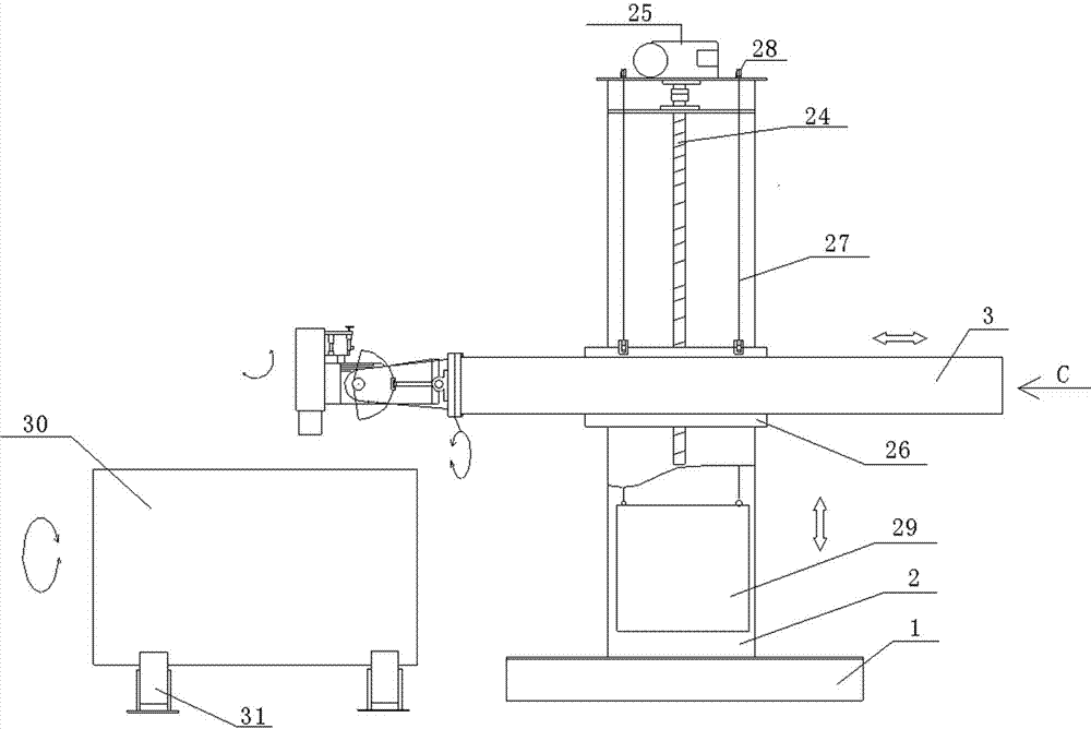
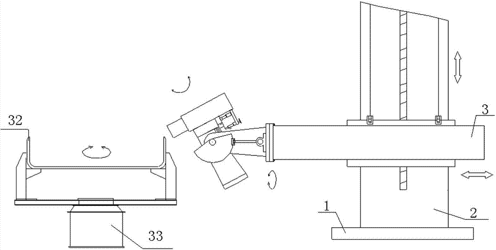
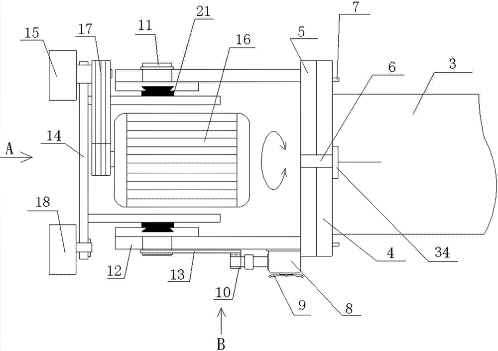
[0031] Such as figure 1 , 2 , 3, 4, 5, 6, 7 and 8, the present invention includes a base 1, the base 1 is provided with a vertical column 2, the column 2 is provided with a horizontal cross arm 3, and the cross arm 3 passes through the lifting device along the The column 2 lifts up and down, and the cross arm 3 moves left and right along the column 2 through the left and right moving device. The left end of the cross arm 3 is provided with an abrasive belt grinding head mounting seat (not marked in the figure); the abrasive belt grinding head mounting seat passes through the first rotating shaft 6 It is rotatably connected with the cross arm 3, and the abrasive belt grinding head mounting seat rotates around the circumference of the cross arm 3; the abrasive belt ...


PUM


Abstract

The invention discloses a tank body multi-angle polishing grinding machine. A stand column is arranged on a base. A cross arm is arranged on the stand column, goes up and down along the stand column through a lifting device and moves left and right along the stand column through a left-right movement device. An abrasive belt grinding head mounting base is arranged at the left end of the cross arm and rotationally connected with the cross arm through a first rotary shaft. The abrasive belt grinding head mounting base rotates around the cross arm. An abrasive belt grinding head is arranged on the abrasive belt grinding head mounting base and rotationally connected with the abrasive belt grinding head mounting base through a second rotary shaft peripherally. The central line of the first rotary shaft is perpendicular to the central line of the second rotary shaft. The abrasive belt grinding head swings around the second rotary shaft peripherally. The abrasive belt grinding head comprises a supporting base fixed to the second rotary shaft. An abrasive belt grinding polishing device and an abrasive belt driving device are arranged on the supporting base. A barrel and an end socket of a tank body can be ground and polished through one abrasive belt grinding head, the power of an adopted motor is low, the energy consumption is low, cost can be lowered, and the equipment investment can be reduced.

Description

technical field [0001] The invention relates to a polishing mill, in particular to a tank body multi-angle polishing mill. Background technique [0002] At present, in the traditionally used tank or container polishing process, two equipments, the barrel polisher and the head polisher, are used to grind and polish the barrel and head of the tank or container respectively. The processing time is long and the polished After the head and the cylinder are welded, when the cylinder is polished again, the outer surface of the head will be polluted again. However, the head cannot be polished after the head and the cylinder are welded. Processing brings great inconvenience. [0003] The prior art also discloses a tank head integrated polishing machine, which is provided with two cross arms, and the two cross arms are arranged side by side on the column through the hanging board, and one end of the two cross arms is Equipped with a polishing device, the equipment investment is high...

Claims


Application Information

Patent Timeline
Patent Type & Authority Applications(China)
IPC IPC(8): B24B21/00B24B21/18
CPCB24B21/00B24B21/18
Inventor 王国民童剑锋彭琦张振海
Owner 南阳龙腾专用车制造有限公司
Why Eureka
Try Eureka