A prefabricated reinforced concrete U-shaped frame beam and its connecting steel frame
A technology of reinforced concrete and frame beams, which is applied to joists, girders, truss beams and other directions, can solve the problems of tying of stirrups, difficult to vibrate and compact concrete, poor close occlusal grip and other problems, and achieves broad application prospects, Good strength and stiffness, convenient construction effect
- Summary
- Abstract
- Description
- Claims
- Application Information
AI Technical Summary
Problems solved by technology
Method used
Image
Examples
Embodiment 1
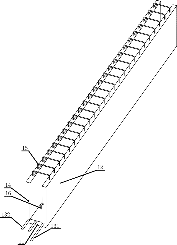
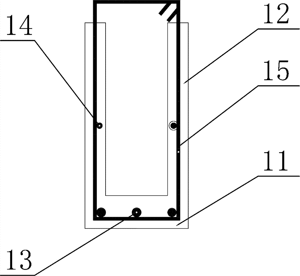
[0057] As shown in Figure 1(a) and Figure 1(b), a fabricated reinforced concrete U-shaped frame beam of the present invention includes a bottom plate 11 and a side plate 12, and the bottom plate 11 is equipped with bottom plate longitudinal reinforcement 13, which is a frame beam The first row of longitudinal reinforcement at the bottom, the longitudinal reinforcement 14 for torsional structure is arranged in the side plate 12, and the stirrups 15 are arranged around the beam, protruding from the top of the side plate 12. Thickness requirements. The longitudinal ribs 13 of the bottom plate protrude from both ends of the beam, and the first longitudinal rib from the right facing the end of the beam is longer than the other longitudinal ribs; the bottom plate 11 protrudes several reinforcement pins 16 inwards, so that the prefabricated U-shaped frame The beam can be reliably connected with the concrete in the post-pouring groove, and the integrity is good.
Embodiment 2
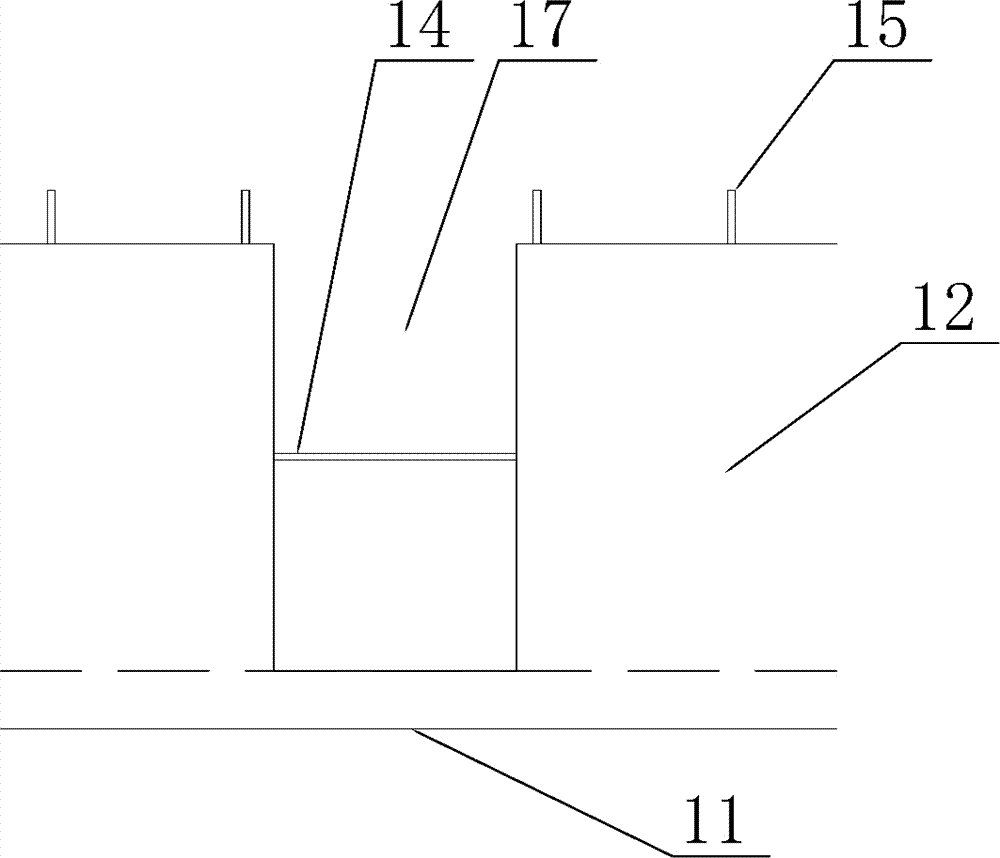
[0059] Such as figure 2 As shown, a prefabricated reinforced concrete U-shaped frame beam of the present invention is based on Embodiment 1, and the vertical intersection of the side plate 12 and the secondary beam is provided with a gap 17 for the secondary beam to pass through vertically. The plates 12 are disconnected and the longitudinal ribs 14 of the torsional structure remain connected. figure 2 The prefabricated reinforced concrete U-shaped frame beam is the main beam, and the secondary beam is placed on the main beam. The bottom of the main beam is lower than the bottom of the secondary beam, and the bottom plate 11 of the main beam is not broken. The width of the gap 17 can accommodate the insertion and removal of the secondary beam.
Embodiment 3
[0061] Such as Figure 3-6 Shown, a kind of mold of the present invention makes the prefabricated reinforced concrete U-shaped frame girder described in embodiment 1 and 2, and this mold comprises: outer mold 21, beam end outer baffle plate 23, U-shaped thin steel channel inner mold 22 , end mold U-shaped hoop 24, outer mold pull bar 25, sleeve pipe 26, U-shaped groove 27; described U-shaped thin steel channel inner mold 22, outer mold 21, beam end outer baffle plate 23 and end mold U-shaped hoop 24 are combined into an inverted U-shaped frame beam mold; the U-shaped thin steel channel inner mold 22 is filled with sand 42, and the particle diameter of the sand 42 is less than 5mm; the U-shaped thin steel channel inner mold 22 is vertically arranged on the outer periphery There are stirrups 15; the U-shaped groove 27 is embedded in the base layer 41 of the site corresponding to the position of the stirrups 15; the U-shaped thin steel channel inner mold 22 and the outer mold 21 ...
PUM
 Abstract
Description
Claims
Application Information
 - R&D
- Intellectual Property
- Life Sciences
- Materials
- Tech Scout
- Unparalleled Data Quality
- Higher Quality Content
- 60% Fewer Hallucinations
Browse by: Latest US Patents, China's latest patents, Technical Efficacy Thesaurus, Application Domain, Technology Topic, Popular Technical Reports.
© 2025 PatSnap. All rights reserved.Legal|Privacy policy|Modern Slavery Act Transparency Statement|Sitemap|About US| Contact US: help@patsnap.com


