
Wearable physiological resonance simulation system, electric stimulation device and physiological activity sensing device

A physiological stimulation and electrical stimulation technology, applied in psychological devices, hypnotic devices, devices that induce sleep or relaxation, etc., can solve the problems of inability to maintain stable contact for a long time, unstable contact between electrodes and skin, and reduced signal quality.

Inactive Publication Date: 2017-08-01
周常安
View PDF16 Cites 9 Cited by
  • Summary
  • Abstract
  • Description
  • Claims
  • Application Information

AI Technical Summary

Problems solved by technology

[0006] However, because the space in the ear canal is very narrow, not only the positioning of the electrodes is not easy, but also the making of the sampling device becomes very complicated, and it is not easy to implement. Moreover, there is also a problem in sampling in the ear canal, ear wax, ear wax, etc. The ear wax in the ear canal is a substance naturally produced by the human body. It will reduce the contact area between the electrode and the skin of the ear canal, or even completely isolate it. It is not easy to achieve a good contact between the electrode and the skin. Cleaning is actually a rather cumbersome process for users
[0007] Furthermore, when the electrodes are placed within the range between the auricle and the skull, since this range is close to the plane of the skull, to maintain the contact between the electrodes and this plane, the force must be fixed towards the skull. , but there is no structure in the pinna to provide force in this direction. Therefore, how to fix the electrodes has always been the most important problem to be overcome. At the same time, it is necessary to pay attention not to sacrifice the comfort of use in order to maintain the stable contact of the electrodes.
[0008] For example, in US2006 / 009497, the reference electrode (reference electrode) is installed on the earlobe using the existing common clamping method, and the detection electrode (detection electrode) is fixed by using the physiological structure of the auricle. Although this method has good intentions, it is obvious that due to the almost complete lack of fixing force, the detection electrodes are actually difficult to be fixed, and the contact between the electrodes and the skin is quite unstable, and it is easy to break due to head rotation, movement, etc. Vibration occurs, which directly affects the quality of the obtained signal
[0009] In addition, in US8565852, in order to fix the detection electrode (detection electrode) in the triangular fossa (triangular fossa) and the space between the crus of helix (crus of helix) and the upper crus of anthelix (superior crux of anthelix), and make the electrodes contact In this space, a special-shaped clamp is used for the area close to the skull. However, for users, it is easy to feel uncomfortable due to the force of the clamp after long-term use. Another way to maintain the detection electrode at the intended contact position is the ear hook structure. However, it can be found that the electrode is still prone to shaking because it cannot provide the force directly applied to the electrode in this way. Therefore, the contact between the electrode and the skin The contact cannot be kept stable for a long time, which will naturally cause the signal quality to degrade
[0010] In US2012 / 0209101, although the ear-shaped hearing aid is used to carry the electrodes and ensure the contact between the electrodes and the ear canal and the skin of the auricle, in this way, the fixing force mainly comes from the part entering the ear canal and the ear canal friction force, and the shape of the hearing aid and the pendant extending behind the ear are only used for positioning, and the electrodes outside the ear canal lack the force of direct fixation. Therefore, as long as there is looseness between the part entering the ear canal and the ear canal, the electrodes will be detached The surface of the pinna skin is still prone to unstable electrode contact
[0011] In addition, in US20070112277, in addition to the implementation of placing electrodes in the ear canal, it also discloses that the electrodes are placed on the surface of the shell behind the ear to contact the head, which is very common in ear-worn brain activity detection devices. Common setting methods and contact positions, however, such a structure is not easy to make the shell behind the ear generate force toward the head, so usually the shell behind the ear is only maintained behind the ear, which is very easy to shake, and the gap between the electrode and the skin Contact is not stable

Method used


Image

  • Wearable physiological resonance simulation system, electric stimulation device and physiological activity sensing device
  • Wearable physiological resonance simulation system, electric stimulation device and physiological activity sensing device
  • Wearable physiological resonance simulation system, electric stimulation device and physiological activity sensing device

Examples


Embodiment Construction

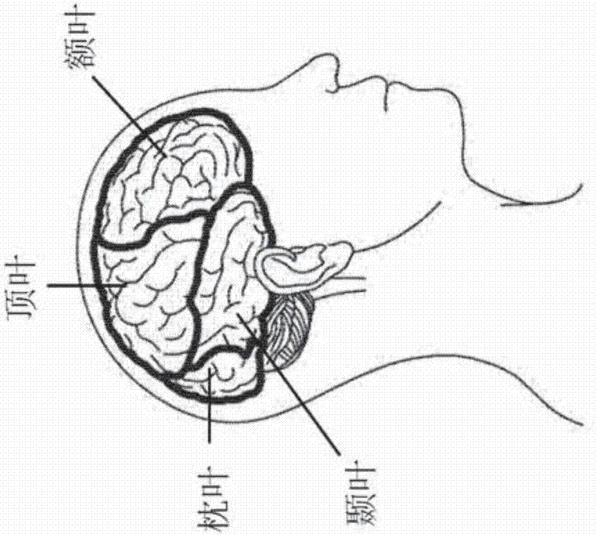
[0066] First, see figure 1 , which is a schematic diagram of the position of the cerebral cortex in the skull and the position of the auricle. It can be seen from the figure that the cerebral cortex falls on the upper half of the skull, and the auricle (also called pinna) is located on both sides of the skull. And protruding outside the skull, which, roughly speaking, is separated by the ear canal, and the cerebral cortex falls roughly on the inner side of the upper ear canal.

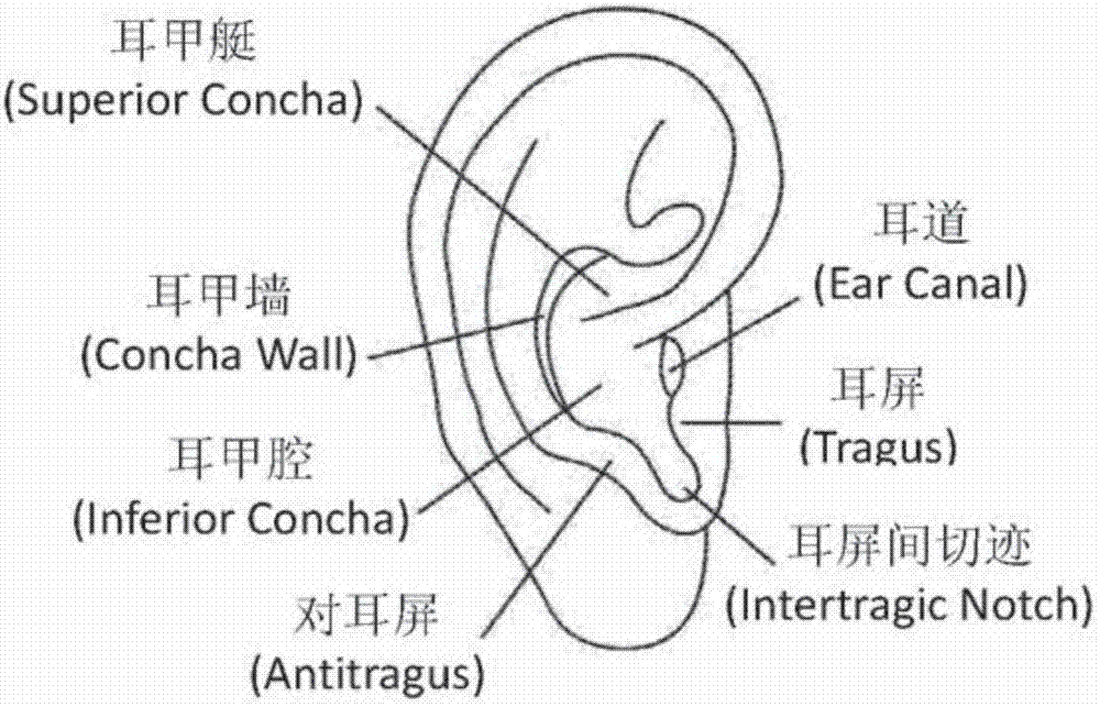
[0067] The experimental results show that a good EEG signal can be measured at the upper part of the auricle, and the EEG signal becomes weaker as it goes down. After observing the physiological structure of the head, it should be because the upper auricle corresponds to the cranium The inside is the position of the cerebral cortex, so in this case, through the transmission of the skull and ear cartilage, brain waves can be measured at the upper part of the auricle, while the lower part of the auricle ...


PUM


Abstract

The invention discloses a wearable physiological resonance simulation system, an electric stimulation device and a physiological activity sensing device. The wearable physiological resonance simulation system is installed on the head and / or ears of a user by an ear-wearing structure, and the simulation applied to the user is adjusted by using a brain electric signal as the foundation, so that the effect of influencing the physiological state, the brain state, and / or the conscious state of the user can be achieved.

Description

technical field [0001] The present invention relates to a wearable physiological resonance stimulation system, an electrical stimulation device and a physiological activity sensing device, in particular to a wearable structure installed on the user's head and / or ear to perform stimulation and sensing on the user. Wearable physiological resonance stimulation system, electrical stimulation device and physiological activity sensing device for measuring physiological activity. Background technique [0002] Traditionally, the electrical activity of the brain measured by placing electrodes on the scalp is called an electroencephalogram (EEG), which can be used to detect and diagnose many physiological conditions, and the obtained brain Activity information can also have many other applications, for example, learning concentration, fatigue, and brain computer interface (braincomputer interface, BCI) and so on. [0003] Generally speaking, there are two ways to measure brain electr...

Claims


Application Information

Patent Timeline
IPC IPC(8): A61B5/0476A61B5/0402A61B5/0478A61B5/0496A61B5/0205A61B5/1455A61B5/16A61B5/18A61B5/00A61B5/0488A61B5/04A61N1/36A61H39/00A61M21/02A61M21/00A61B5/11
CPCA61B5/0205A61B5/02438A61B5/08A61B5/1118A61B5/14551A61B5/168A61B5/18A61B5/4806A61B5/6802A61B5/6803A61B5/681A61B5/6817A61B5/746A61B2503/22A61H39/002A61M21/00A61M21/02A61M2021/0022A61M2021/0027A61M2021/0055A61N1/36014A61B5/24A61B5/291A61B5/318A61B5/369A61B5/389A61B5/398G02C5/22G02C11/00G02C11/10
Inventor 周常安
Owner 周常安
Learn More