
Full-automatic bar bonding unit for bonding crystal bars

A fully automatic, crystal ingot technology, applied in the direction of crystal growth, conveyor objects, fine working devices, etc., can solve the problems of laborious and time-consuming handling process, low degree of automation, and low work efficiency, so as to prevent the phenomenon of waiting for materials and automate The effect of high degree and high positioning accuracy

Active Publication Date: 2017-08-01
TIANJIN ZHONGHUAN SEMICON CO LTD
View PDF2 Cites 12 Cited by
  • Summary
  • Abstract
  • Description
  • Claims
  • Application Information

AI Technical Summary

Problems solved by technology

In the production process of silicon wafers, the bonding of crystal rods is an essential step in the production process, but it is also a link with a relatively low degree of automation.
At present, most manufacturers rely on manual labor to complete the ingot bonding process. The degree of automation is low. The weight of the tooling and the bonded ingot can reach 100KG. The handling process is laborious and time-consuming, with low work efficiency and high labor intensity.

Method used


Image

  • Full-automatic bar bonding unit for bonding crystal bars
  • Full-automatic bar bonding unit for bonding crystal bars
  • Full-automatic bar bonding unit for bonding crystal bars

Examples


Embodiment Construction

[0031] It should be noted that, in the case of no conflict, the embodiments of the present invention and the features in the embodiments can be combined with each other.

[0032] In describing the present invention, it should be understood that the terms "center", "longitudinal", "transverse", "upper", "lower", "front", "rear", "left", "right", The orientations or positional relationships indicated by "vertical", "horizontal", "top", "bottom", "inner", "outer", etc. are based on the orientation or positional relationship shown in the drawings, and are only for the convenience of describing the present invention Creation and simplified description, rather than indicating or implying that the device or element referred to must have a specific orientation, be constructed and operate in a specific orientation, and therefore should not be construed as limiting the invention. In addition, the terms "first", "second", etc. are used for descriptive purposes only, and should not be und...


PUM


Abstract

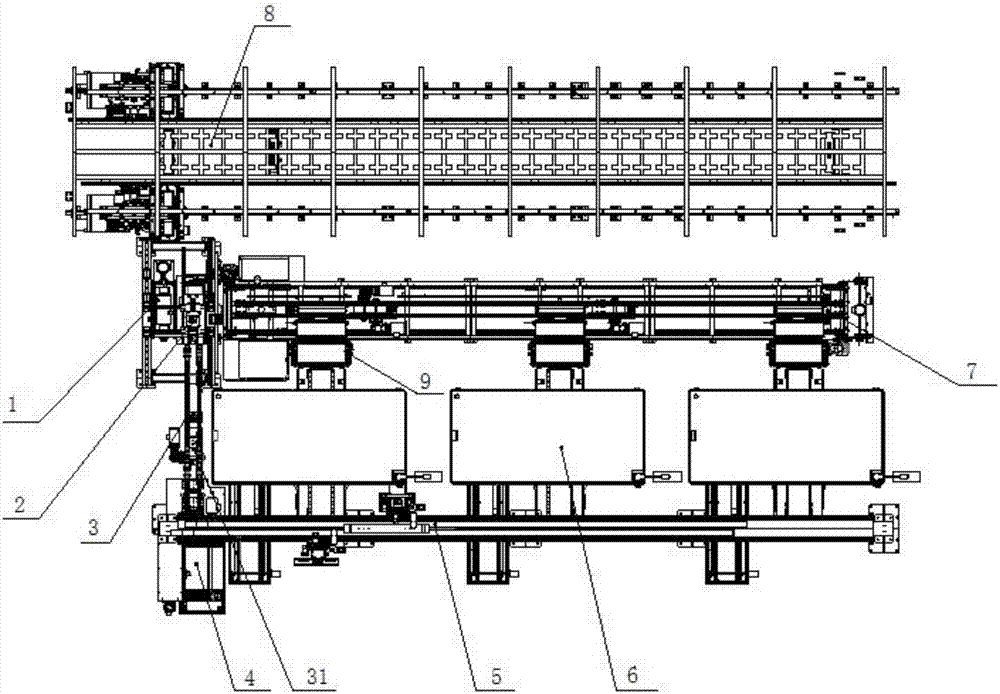
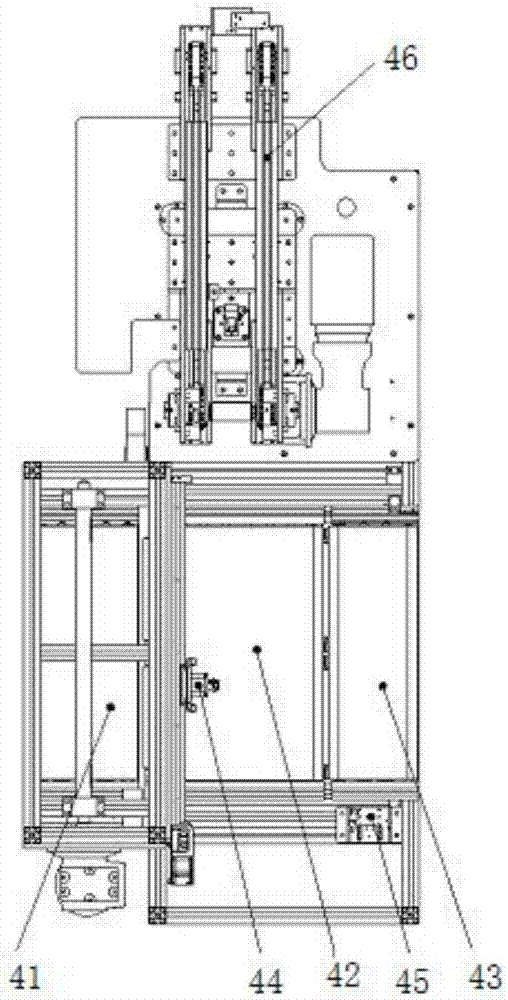
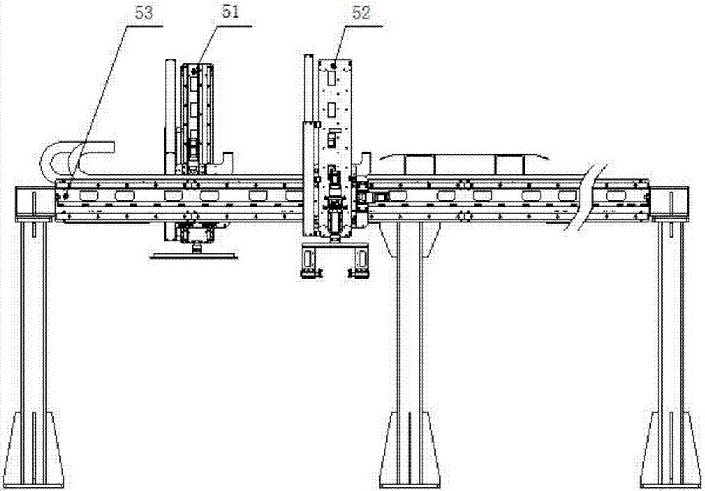
The invention provides a full-automatic bar bonding unit for bonding crystal bars. The full-automatic bar bonding unit for bonding the crystal bars comprises a material base feeding mechanism, a crystal bar feeding mechanism, a splitting mechanical arm, a jig return line, bar bonding machines, a truss mechanical arm, a pre-curing assembly line and a digital curing library, wherein the splitting mechanical arm is used for grabbing material bases provided by the material base feeding mechanism, the two ends of the jig return line are connected to the splitting mechanical arm and the crystal bar feeding mechanism in a butt joint mode respectively, a sliding rail of the truss mechanical arm is arranged above the feeding end of the bar bonding machines and above the crystal bar feeding mechanism, the feeding ends of the pre-curing assembly line correspond to the discharging ends of the bar bonding machines, the discharging end of the pre-curing assembly line is located below the splitting mechanical arm, and the feeding end of the digital curing library is connected to the splitting mechanical arm in a in butt joint mode. The full-automatic bar bonding unit has the advantages that automation and manpower minimization of bar bonding procedures can be realized, the labor intensity of workers can be reduced, and meanwhile, the production efficiency can be greatly improved.

Description

technical field [0001] The invention belongs to the technical field of crystal rod processing, and in particular relates to a fully automatic sticking unit for bonding crystal rods. Background technique [0002] With the technological development of the photovoltaic industry, manufacturers have higher and higher requirements for the automation of related production equipment. In the production process of silicon wafers, the bonding process of ingots is an essential step in the production process, but it is also a link with a relatively low degree of automation. At present, most manufacturers rely on manual labor to complete the ingot bonding process. The degree of automation is low. The weight of the tooling and the bonded ingot can reach 100KG. The handling process is laborious and time-consuming, with low work efficiency and high labor intensity. . Contents of the invention [0003] In view of this, the present invention aims to propose a fully automatic rod sticking u...

Claims


Application Information

Patent Timeline
Patent Type & Authority Applications(China)
IPC IPC(8): B65G47/90B28D7/00B28D5/00C30B33/06H01L31/18
CPCH01L31/1876C30B33/06B65G47/90B28D5/00B28D7/00
Inventor 靳立辉张学强王国瑞崔振强陈志达姚长娟渠丽岩杨海亮杨明丁吉祥张华帅赵晓光尹擎
Owner TIANJIN ZHONGHUAN SEMICON CO LTD
Learn More