Natural gas single well multiphase flow metering equipment
A metering equipment, multiphase flow technology, applied in the direction of measurement, production of fluid, wellbore/well components, etc., can solve the problems of complex construction, high test cost, large equipment, etc., to achieve large measurement contact surface, improve separation effect, The effect of reducing equipment investment
- Summary
- Abstract
- Description
- Claims
- Application Information
AI Technical Summary
Problems solved by technology
Method used
Image


Examples
Embodiment 1
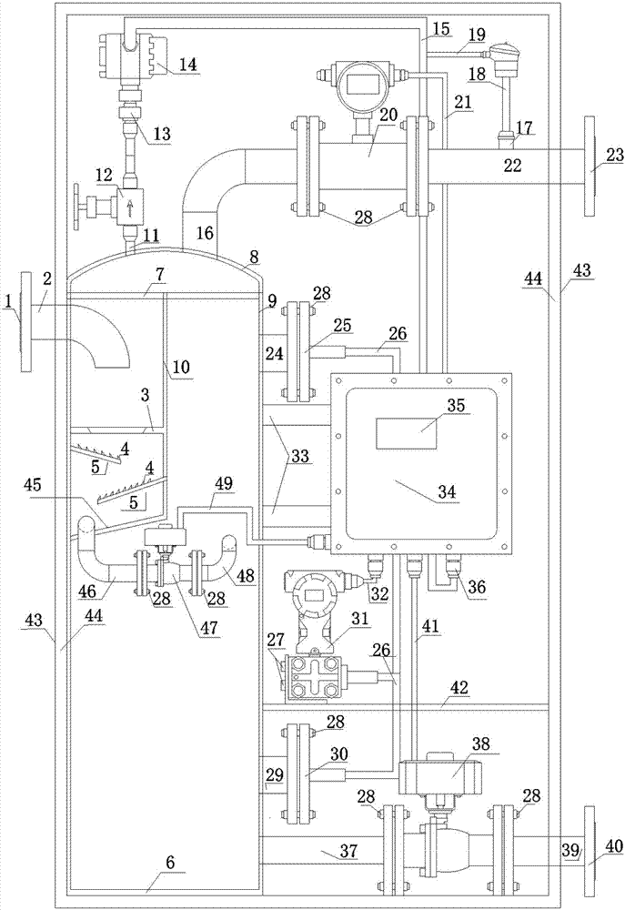
[0027] A natural gas single well multiphase flow metering equipment, such as figure 1 As shown, including gas-liquid separation container system, gas metering system, liquid metering control system, pressure measuring element, temperature measuring element and signal processing system;
[0028] The gas-liquid separation container system includes an inlet connection flange 1, an inlet pipe 2, a liquid inlet baffle 3, sawtooth 4, an inclined baffle 5, a separation container bottom plate 6, a gas-liquid separation net 7, a separation container topping 8, a separation The container cylinder 9, the separator 10 and the bottom plate of the separation chamber 45; the separation container topping 8 is welded on the upper part of the separation container cylinder 9, the separation container bottom plate 6 is welded on the bottom of the separation container cylinder 9, and the gas-liquid separation net 7 is welded on the separation container cylinder 9 The upper part, the inlet connecti...
Embodiment 2
[0036] A single-well multiphase flow metering device for natural gas, similar to Embodiment 1, the difference is that the metering device also includes a box assembly, and the box assembly includes a box shell 43; a gas-liquid separation container system, a gas The metering system, the liquid metering control system, the pressure measuring element, the temperature measuring element and the signal processing system are arranged in the box shell 43 .
[0037] In this way, all its measuring components are placed in the box shell 43, so as to prevent the measuring system from being exposed to the wind and the sun, and to avoid premature aging and damage of the measuring instruments caused by environmental factors.
Embodiment 3
[0039] A single-well multiphase flow metering device for natural gas is similar to Embodiment 2, the difference is that the box assembly also includes an insulation layer 44 , and the insulation layer 44 is attached to the inner wall of the box shell 43 .
[0040] In this way, it adopts the self-insulation design idea, which can avoid the damage to the measurement system (especially avoid the freezing of the liquid in the separation container) under the low temperature working conditions in the wild in the north, so that the instrument is still not easy to be damaged in the low temperature environment. .
PUM
 Abstract
Description
Claims
Application Information
 - R&D
- Intellectual Property
- Life Sciences
- Materials
- Tech Scout
- Unparalleled Data Quality
- Higher Quality Content
- 60% Fewer Hallucinations
Browse by: Latest US Patents, China's latest patents, Technical Efficacy Thesaurus, Application Domain, Technology Topic, Popular Technical Reports.
© 2025 PatSnap. All rights reserved.Legal|Privacy policy|Modern Slavery Act Transparency Statement|Sitemap|About US| Contact US: help@patsnap.com