Attack angle variation method for H-shaped vertical-axis wind turbine and device thereof

A wind turbine, vertical axis technology, applied in wind engine control, wind engine monitoring, wind engine, etc., can solve the static data of the airfoil without considering the dynamic stall of the vertical axis wind turbine, and the research results cannot fully reflect the actual situation , It is difficult to adapt to different wind speeds, etc., to achieve the effect of improving self-starting performance, increasing wind energy utilization, and improving power generation efficiency

Inactive Publication Date: 2017-08-04
CHINA UNIV OF PETROLEUM (EAST CHINA)
View PDF7 Cites 2 Cited by
  • Summary
  • Abstract
  • Description
  • Claims
  • Application Information

AI Technical Summary

Problems solved by technology

However, in terms of structure, the blade angle-of-attack adjustment devices designed by Yan Qiang and Lian Zhengguang both use a cam mechanism, which is difficult to adapt to different wind speeds; the prototype used by Zhang Lixun et al. Separately control the change of the angle of attack of the two blades, which increases the inertia of the system, and the adjustment method has a certain hysteresis
In addition, theoretically, in the analysis of the aerodynamic characteristics of the above research, it is assumed that the induced velocities in all directions in the downwind area of ​​the vertical axis rotor are consistent in size and direction; although these assumptions simplify the calculation, the research results cannot fully reflect the actual situation; and the adopted The static data of the airfoil does not consider the dynamic stall problem of the vertical axis wind turbine under the actual working conditions

Method used


Image

  • Attack angle variation method for H-shaped vertical-axis wind turbine and device thereof
  • Attack angle variation method for H-shaped vertical-axis wind turbine and device thereof
  • Attack angle variation method for H-shaped vertical-axis wind turbine and device thereof

Examples


Embodiment Construction

[0090] In order to make the technical means, creative features, goals and effects achieved by the present invention easy to understand, the following embodiments are combined with the accompanying drawings to describe a method for changing the angle of attack of an H-type vertical axis wind power generator and a real-time adjustment device for the angle of attack of the present invention. Make specific explanations.

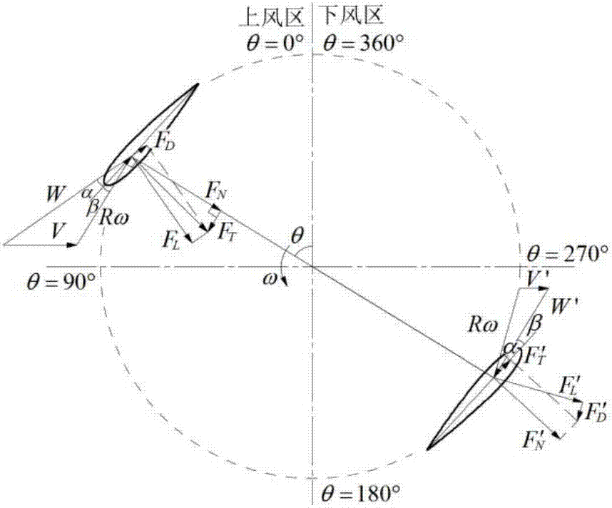
[0091] From figure 2 , that is, the force analysis diagram of the blade shows that to calculate the angle of attack of the blade in each azimuth, the induced velocities in each azimuth of the upwind area and the downwind area, and their induction factors must be calculated first.

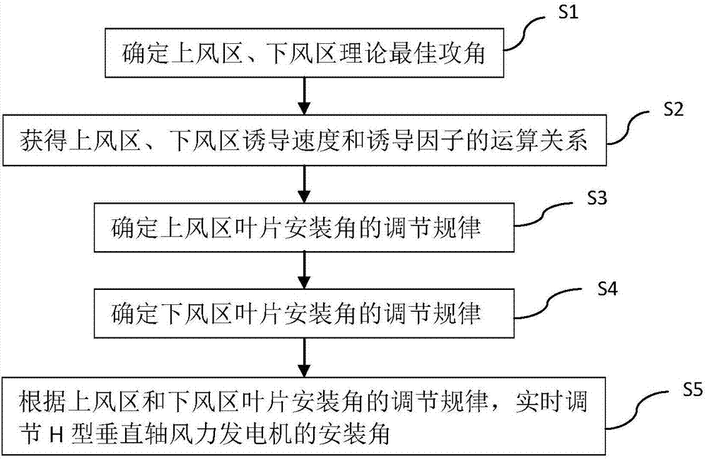
[0092] The method for changing the angle of attack of the H-type vertical axis wind power generator in the embodiment of the present invention, the steps are as follows:

[0093] S1. Determine the theoretical optimal angle of attack for the upwind area and the downwind area. The spec...


PUM


Abstract

The invention provides an attack angle variation method for an H-shaped vertical-axis wind turbine. The attack angle variation method comprises the following steps that (1) the theoretical optimum attack angles of an upper wind area and a lower wind area are determined; (2) the operation relations of the induced velocities and the inducing factors of the upper wind area and the lower wind area are obtained; (3) the adjusting law of the mounting angle of blades of the upper wind area is determined; (4) the adjusting law of the mounting angle of blades of the lower wind area is determined; and (5) according to the adjusting laws of the mounting angles of the blades of the upper wind area and the lower wind area, the mounting angle of the H-shaped vertical-axis wind turbine is adjusted in real time. The invention further provides an attack angle real-time adjusting device of the H-shaped vertical-axis wind turbine. By using the attack angle variation method for the H-shaped vertical-axis wind turbine, the blade attack angle is adjusted in real time, so that the attack angles of all positions of the blades in the rotating process are closest to the optimum attack angles, and the purpose that the wind energy utilization ratio is increased is achieved accordingly.

Description

technical field [0001] The invention belongs to the technical field of new energy, and in particular relates to a method for changing the angle of attack of an H-type vertical axis wind power generator and a real-time adjustment device for the angle of attack. Background technique [0002] At present, the wind energy utilization rate of vertical axis wind turbines is only about 35%, which is far lower than the theoretical value of 66.6%. This shortcoming hinders its large-scale development. The synthetic wind speed of the vertical axis wind turbine refers to the vector sum of the incoming wind speed and the tangential wind speed. The angle of attack of the blade refers to the angle between the synthetic wind speed and the blade chord line. The installation angle of the blade refers to the angle between the blade chord line and the tangent line of the wind rotor. angle. Among them, the blade angle of attack is one of the most important factors affecting the wind energy utili...

Claims


Application Information

Patent Timeline
IPC IPC(8): F03D7/06F03D9/25F03D17/00
CPCF03D7/06Y02E10/74
Inventor 张立军马东辰米玉霞赵昕辉顾嘉伟王旱祥刘延鑫刘永红
Owner CHINA UNIV OF PETROLEUM (EAST CHINA)
Why Eureka
Try Eureka