PEMS plasma enhancing magnetron sputtering coating device

A magnetron sputtering coating and plasma technology, which is applied in the field of plasma-enhanced magnetron sputtering coating equipment, can solve the problem that the atomic or molecular ionization rate of the membrane material cannot meet the requirements of high-tech products, and achieve enhanced cleaning effect and attached Focus on improving the coating speed and enhancing the effect of ionization

Inactive Publication Date: 2017-08-08
沈阳科友真空技术有限公司
View PDF5 Cites 5 Cited by
  • Summary
  • Abstract
  • Description
  • Claims
  • Application Information

AI Technical Summary

Problems solved by technology

[0004] Although the plasma-enhanced magnetron sputtering coating technology can achieve the effect of enhancing the plasma and increasing the ionization rate, the ionization rate of the atoms or molecules of the film material still cannot meet the needs of high-tech products.

Method used


Image

  • PEMS plasma enhancing magnetron sputtering coating device
  • PEMS plasma enhancing magnetron sputtering coating device
  • PEMS plasma enhancing magnetron sputtering coating device

Examples


Embodiment Construction

[0027] In order to make the object, technical solution and advantages of the present invention clearer, the present invention will be further described in detail below in conjunction with the accompanying drawings and examples, but the given examples are not intended to limit the present invention.

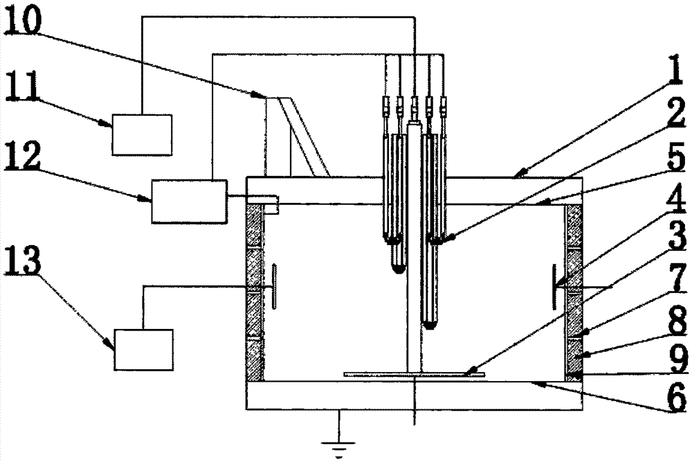
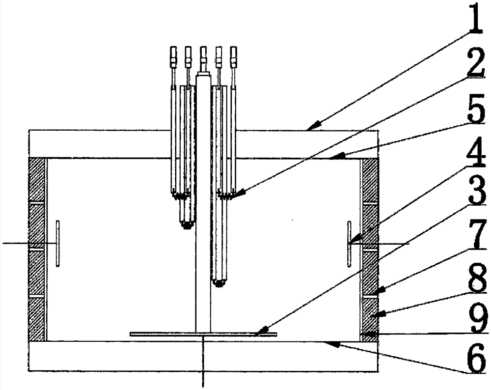
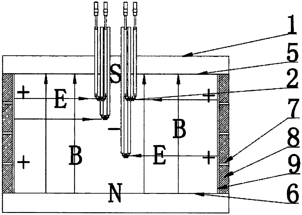
[0028] Such as Figure 1 to Figure 3 As shown, the embodiment of the present invention includes a vacuum chamber 1, an upper cover lifting mechanism 10 and a power supply, and the vacuum chamber 1 is provided with a cathode tungsten wire 2, a magnetic pole plate, a magnetron target 4 and a workpiece table 3, and the cathode tungsten wire 2 passes through the filament The fixed column is fixed at the top center of the vacuum chamber 1, and the cathode tungsten wires 2 are arranged in an orderly manner around the center of the vacuum chamber 1. The magnetic pole plates include an upper magnetic pole plate 5 and a lower magnetic pole plate 6, and the upper magnetic pole plate 5 is arr...


PUM


Abstract

The invention provides a PEMS plasma enhancing magnetron sputtering coating device and relates to the technical field of vacuum sputtering coating. The PEMS plasma enhancing magnetron sputtering coating device comprises a vacuum chamber, an upper cover lifting mechanism and a power source. Cathode tungsten filaments, a magnetic pole plate, a magnetic control target and a workpiece table are arranged in the vacuum chamber. The cathode tungsten filaments are fixed to the center position of the top end of the vacuum chamber through filament fixing pillars. The cathode tungsten filaments are arranged in order around the center position of the vacuum chamber. The magnetic pole plate comprises an upper magnetic pole plate body and a lower magnetic pole plate body, wherein the upper magnetic pole plate body is arranged at the top end of the vacuum chamber, and the lower magnetic pole plate body is arranged at the bottom end of the vacuum chamber. The worktable is located above the lower magnetic pole plate body. The magnetic control target comprises a left magnetic control target body and a right magnetic control target body, wherein the left magnetic control target body is arranged at the left end of the vacuum chamber, the right magnetic control target body is arranged at the right end of the vacuum chamber, and the left magnetic control target body and the right magnetic control target body are oppositely arranged. By means of the PEMS plasma enhancing magnetron sputtering coating device, the electron number can be increased, the collision probability between electrons or membrane material atoms or molecules is further improved by constraining the electron movement track through a magnetic field, and therefore the ionization rate is increased.

Description

technical field [0001] The invention relates to the technical field of vacuum sputtering coating, in particular to a PEMS plasma enhanced magnetron sputtering coating equipment. Background technique [0002] With the rapid development of magnetron sputtering coating technology in recent years, this technology has become more and more widely used in the fields of machinery, aerospace, decoration and food packaging, and has become the mainstream technology in vacuum coating technology. The principle is that in the vacuum chamber, the electric field is used to ionize the working gas, and the ionized ions are bound by the magnetic field orthogonal to the electric field to continuously bombard the target near the target, and the material on the target is sputtered and deposited on the surface of the workpiece. [0003] Plasma Enhanced Magnetron Sputtering (Plasma Enhanced Magnetron Sputtering) coating technology, abbreviated as PEMS, on the basis of the original magnetron sputter...

Claims


Application Information

Patent Timeline
Patent Type & Authority Applications(China)
IPC IPC(8): C23C14/35
CPCC23C14/355
Inventor 渠洪波
Owner 沈阳科友真空技术有限公司
Why Eureka
Try Eureka