
Sweep frequency laser light source based on liquid crystal tuning filtering device

A tuning filter and laser light source technology, applied in the field of optics, can solve the problems of high fabrication, shallow imaging depth, inability to achieve precise tuning, etc., and achieve the effect of ensuring stability

Inactive Publication Date: 2017-08-11
UNIV OF SHANGHAI FOR SCI & TECH
View PDF4 Cites 0 Cited by
  • Summary
  • Abstract
  • Description
  • Claims
  • Application Information

AI Technical Summary

Problems solved by technology

In order to achieve the ideal light source quality, the stepper motor needs to have high precision and high repeatability, so it is made into a higher
Moreover, this kind of filter is mainly tuned through the mechanical structure, which is easily disturbed by external vibration and has poor stability.
[0007] 2. Optical fiber Fabry-Perot tuned filter, the instantaneous line width is extremely fine, but the free spectral range is small, the axial resolution of imaging is not high, and the image accuracy is not enough
[0008] 3. Acousto-optic tuning filter, no mechanical movement, strong anti-interference, fast tuning speed, but the instantaneous line width of the output light is large, precise tuning cannot be achieved, and the imaging depth is limited
The liquid crystal filter type filter is easy to manufacture and has a wide free spectral range, but the spectral bandwidth is large, which will make the instantaneous line width of the light source large, resulting in a shallow imaging depth and the formed image is not fine enough
[0013] At present, CRI and Meadowlark in the United States have commercialized liquid crystal filter type filters, but these products are statically tuned filters and are not suitable for continuously tuned frequency-sweeping laser light sources.

Method used


Image

  • Sweep frequency laser light source based on liquid crystal tuning filtering device
  • Sweep frequency laser light source based on liquid crystal tuning filtering device
  • Sweep frequency laser light source based on liquid crystal tuning filtering device

Examples


Embodiment Construction

[0030] The specific implementation manner of the present invention will be described below in conjunction with the accompanying drawings and examples.

[0031]

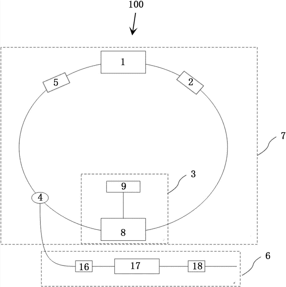
[0032] figure 1 It is a structural schematic diagram of a frequency-sweeping laser light source based on a liquid crystal tuning filter device according to an embodiment of the present invention.

[0033] Such as figure 1 As shown, a frequency-sweeping laser light source (hereinafter referred to as a frequency-sweeping laser light source) 100 based on a liquid crystal tuning filter device includes a semiconductor optical amplifier 1, a first optical isolator 2, a tuning filter device 3, a fiber coupler 4, and a second optical isolator 5 and an optical enhancement output module 6 . Among them, the semiconductor optical amplifier 1 , the first optical isolator 2 , the tuning filter device 3 , the fiber coupler 4 and the second optical isolator 5 constitute a ring laser oscillator cavity 7 . In addition, in this emb...


PUM


Abstract

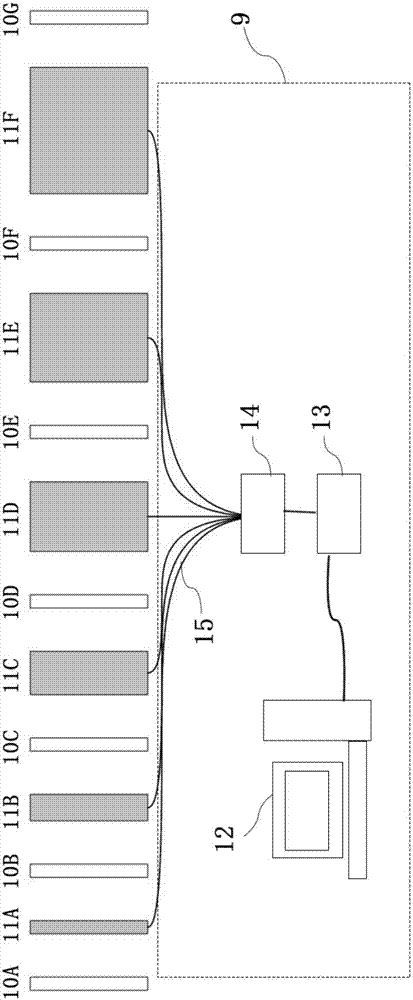
The invention provides a sweep frequency laser light source based on a liquid crystal tuning filtering device, including a semiconductor light amplifier, a tuning filtering device, an optical fiber coupler, and a light enhancement output device. The tuning filtering device comprises a multi-level Lyot filter module and a multi-channel signal generator for driving the multi-level Lyot filter module. The optical fiber coupler is used for dividing the sweep frequency laser into an output sweep frequency laser and a return sweep frequency laser. The multi-level Lyot filter module is an m-level Lyot filter module consisting of m + 1 polaroids and m liquid crystal cells alternately arranged in turn. The multi-channel signal generator has a driving signal generating module, a signal transmission module, a digital-analog conversion module and m electrical signal output ports. The m electrical signal output ports and the m liquid crystal cells are in one-to-one correspondence, and electrical signals are simultaneously loaded to the m liquid crystal cells. The sweep frequency laser light source is based on the liquid crystal technology to achieve tuning filtering, and can provide the sweep frequency laser with the small passband bandwidth.

Description

technical field [0001] The invention belongs to the field of optics and relates to a frequency-sweeping laser light source, in particular to a frequency-sweeping laser light source based on a liquid crystal tuning filter device. Background technique [0002] Optical coherence tomography (OCT) is an emerging non-invasive optical imaging technology that can perform real-time, non-destructive, high-resolution three-dimensional imaging of living tissues. There are good applications in medical diagnosis and even in the field of industrial testing. [0003] OCT mainly includes time-domain OCT, frequency-domain OCT and swept-frequency OCT (Swept Source OCT, SS-OCT). Among them, frequency-swept OCT, as the latest generation of OCT technology, has faster imaging speed, higher dynamic range and better sensitivity, and has a wider application prospect. [0004] The frequency-swept laser light source is a key part of the frequency-swept OCT technology. An ideal frequency-swept laser ...

Claims


Application Information

Patent Timeline
IPC IPC(8): H01S5/50H01S5/00
CPCH01S5/5045H01S5/0078
Inventor 陈明惠贾文宇秦显富何锦涛张浩陶建峰陈志雄
Owner UNIV OF SHANGHAI FOR SCI & TECH
Learn More