Supercharge Your Innovation With Domain-Expert AI Agents!

A method of producing bimetallic composite pipe by traction method

A bimetallic composite pipe and base pipe technology, applied in metal extrusion dies, pipes, rigid pipes, etc., can solve the problems of shortened service life, loss of production enterprises, and increased workload.

Active Publication Date: 2019-02-22
渭南木王智能科技股份有限公司
View PDF7 Cites 0 Cited by
  • Summary
  • Abstract
  • Description
  • Claims
  • Application Information

AI Technical Summary

Problems solved by technology

For example, in the oil transportation industry, a single carbon steel pipe used as a transportation pipe will corrode the pipe when it encounters some acid radical ions contained in the transported medium, which will affect the performance of the pipe and cause a serious problem in the service life of the single carbon steel pipe. It is self-evident that the shortening will cause production stoppage, shutdown, replacement of new tubes, increase of workload, and losses to production enterprises.

Method used


Image

  • A method of producing bimetallic composite pipe by traction method
  • A method of producing bimetallic composite pipe by traction method

Examples


Embodiment 1

[0017] 1. Select a 6.1m-long 77mm×2.4mm seamless stainless steel pipe as the inner lining pipe, and then select a 6m-long 89.5mm×5mm carbon steel pipe as the outer base pipe. The half-cone angle of the cemented carbide tapered extrusion die is 10°, and the cemented carbide tapered extrusion die ( figure 2 ) with a maximum outer diameter of 75.30mm for the test.

[0018] 2. Cut the end of the lined stainless steel tube into 12 evenly distributed shapes with a cutting depth of 70~90mm, and then turn it out and fix it on the outside of the outer tube to realize the fixation between the inner liner and the outer base tube . Then apply mechanical oil and 2000 mesh graphite powder evenly in the inner liner as lubricant.

[0019] 3. Put the pipe section to be processed prepared in process 2 on the workbench and fix it to ensure that the center of the lined pipe is level with the drawbar.

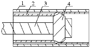
[0020] 4. Press figure 1 Traction is performed in the manner shown in to achieve compoundi...

Embodiment 2

[0024] A 6.1m-long 44mm×1.8mm seamless stainless steel pipe is selected as the inner lining pipe, and a 6m-long 51mm×3mm carbon steel pipe is selected as the outer base pipe. The semi-cone angle of the cemented carbide tapered extrusion die is 10°, and the maximum outer diameter of the cemented carbide tapered extrusion die is 41.9mm for testing. The remaining steps are carried out with reference to the procedure in Example 1. The test results show that the bonding strength of the prepared pipe is 0.55MPa.

Embodiment 3

[0026] A 6.1m long 130mm×3.0mm seamless stainless steel pipe is selected as the inner lining pipe, and a 6m long 149mm×8mm carbon steel pipe is selected as the outer base pipe. The semi-cone angle of the cemented carbide tapered extrusion die is 10°, and the maximum outer diameter of the cemented carbide tapered extrusion die is 127.40mm for testing. The remaining steps are carried out with reference to the procedure in Example 1. The test results show that the bonding strength of the prepared pipe is 0.54MPa.


PUM

PropertyMeasurementUnit
strengthaaaaaaaaaa
strengthaaaaaaaaaa
strengthaaaaaaaaaa

Abstract

The invention discloses a method for producing bimetallic composite pipes using a traction method, which specifically involves placing an inner lining pipe in an outer base pipe, placing a tapered extrusion die in the inner lining pipe and pulling and moving it by a pull rod, and the inner lining pipe is moved by a cone The extrusion die extrudes and expands and mechanically adheres to the outer base tube to form a bimetallic composite tube. The material of the tapered mold of the present invention is cemented carbide or quenched and tempered No. 45 steel. The inner lining pipe is made of stainless steel pipe, aluminum pipe, titanium alloy pipe or copper alloy pipe, which has corrosion resistance. The outer base pipe is made of carbon steel pipe, which has low price. The low cost and excellent comprehensive mechanical properties ensure the performance of composite pipes under actual complex conditions, and can meet the needs of pipelines in the oil production industry, gas transmission industry, water transportation and other industries.

Description

technical field [0001] The invention relates to a method for producing bimetallic composite pipes by using a traction method. The bimetallic composite pipes produced can meet the requirements for pipelines in industries such as oil production, gas transmission, and water transportation, and belong to the technical field of bimetallic composite pipe material manufacturing. Background technique [0002] Pipeline transportation, as one of the five major modes of transportation alongside railways, highways, water transportation, and aviation, has an extremely wide range of applications in industries that require fluid transportation. In recent years, with the development of the economy and the expansion of industrialization, the media to be transported tends to be diversified, which puts forward higher and higher requirements for the transportation capacity of the pipeline itself. Some of the materials transported by the pipeline are corrosive to a certain extent, and some conta...

Claims


Application Information

Patent Timeline
Patent Type & Authority Patents(China)
IPC IPC(8): B21C23/08B21C25/02F16L9/02
CPCB21C23/085B21C25/02F16L9/02
Inventor 郑茂盛田忠赵渊高航胡军滕海鹏李恒欣
Owner 渭南木王智能科技股份有限公司
Features
  • R&D
  • Intellectual Property
  • Life Sciences
  • Materials
  • Tech Scout
  • Unparalleled Data Quality
  • Higher Quality Content
  • 60% Fewer Hallucinations
Learn More