Wooden craft product grinding and polishing machine

A polishing machine and handicraft technology, applied in grinding/polishing equipment, grinding/polishing safety devices, grinding machine parts, etc., can solve the problems of low processing quality, poor grinding uniformity, low grinding efficiency, etc.

Pending Publication Date: 2017-08-15
CHONGQING IND POLYTECHNIC COLLEGE
View PDF8 Cites 11 Cited by
  • Summary
  • Abstract
  • Description
  • Claims
  • Application Information

AI Technical Summary

Problems solved by technology

[0002] Grinding and polishing technology has become a widely used modern workpiece surface processing technology. In the process of wood processing, wood needs to be cut, carved and other processes, leaving many burrs and burrs on the wood surface, so the wood surface needs to be polished The usual means of processing is to manually carry out smoothness grinding, which has the disadvantages of high specific operation intensity, high labor cost, poor grinding uniformity, and low processing quality. A semi-automatic grinding and polishing tool that appears in the prior art is basically that the workpiece is not If the grinding tool is used for single-item grinding, the grinding efficiency may be low and uneven. On the other hand, this automatic single-line grinding method requires a person to stand in front of the grinder at any time to adjust the workpiece position, which will inevitably inhale a lot of dust, which is not conducive to Health; therefore, it is necessary to realize a grinding and polishing machine in which the workpiece and the grinding machine are linked to each other

Method used


Image

  • Wooden craft product grinding and polishing machine

Examples


Embodiment Construction

[0016] In order to enable those skilled in the art to better understand, the technical solution of the present invention will be further described below in conjunction with the accompanying drawings and embodiments.

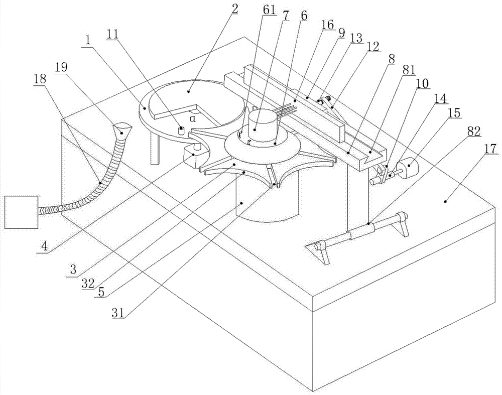
[0017] like figure 1 The wooden handicraft polishing machine shown includes a power system, a sheave mechanism, a crank and rocker mechanism and a polishing brush body. The crank and rocker mechanism is located on the right side of the sheave mechanism, and the sheave mechanism includes a chassis 1. The driving dial 2 and the sheave 3 located above the chassis 1. The driving dial 2 is a convex locking arc with an arc length of 300°. The remaining 60° half of the convex locking arc is removed from the driving dial 2. The arc position α is provided with a cylindrical pin 11 fixed on the chassis 1, the center of the chassis 1 is fixed with a sheave mechanism motor 4 placed below the chassis 1, and the sheave 3 is fixed on the base 5 below through a rotating shaft. ...


PUM


Abstract

The invention relates to the field of machining equipment, in particular to a wooden craft product grinding and polishing machine. The wooden craft product grinding and polishing machine comprises a power system, a sheave mechanism, a crank rocker mechanism and a grinding and polishing brush; the crank rocker mechanism is located on the right side of the sheave mechanism; the sheave mechanism comprises a chassis, a drive plate on the chassis and a sheave; the crank rocker mechanism comprises a sliding groove base, a slide block, a crank and a rocker; the sheave mechanism and the crank rocker mechanism are matched; under driving of a motor of the sheave mechanism, the drive plate and the chassis rotate, a cylindrical pin is inserted into a radial groove to drive the sheave to rotate by one sixth of the circumference once the chassis rotates by one circle, the crank rocker mechanism drives the grinding and polishing brush to slide left and right, the grinding and polishing brush performs grinding and polishing on a rotating workpiece while sliding, and then the effect that the brush and the workpiece move mutually is achieved, the brush grinds and polishes by one or two cycles when the workpiece leans to one side by 60 degrees, and in this way, the workpiece is evenly ground clean by this cyclic rotation.

Description

technical field [0001] The invention relates to the field of processing equipment, in particular to a wooden handicraft grinding and polishing machine. Background technique [0002] Grinding and polishing technology has become a widely used modern workpiece surface processing technology. In the process of wood processing, wood needs to be cut, carved and other processes, leaving many burrs and burrs on the wood surface, so the wood surface needs to be polished The usual means of processing is to manually carry out smoothness grinding, which has the disadvantages of high specific operation intensity, high labor cost, poor grinding uniformity, and low processing quality. A semi-automatic grinding and polishing tool that appears in the prior art is basically that the workpiece is not If the grinding tool is used for single-item grinding, the grinding efficiency may be low and uneven. On the other hand, this automatic single-line grinding method requires a person to stand in fro...

Claims


Application Information

Patent Timeline
IPC IPC(8): B24B9/18B24B41/06B24B55/06B24B47/16B24B47/22B24B27/00B24B41/00
CPCB24B9/18B24B27/0069B24B41/005B24B41/06B24B47/16B24B47/22B24B55/06Y02P70/10
Inventor 张文
Owner CHONGQING IND POLYTECHNIC COLLEGE
Why Eureka
Try Eureka