Pipeline mud conveying device

A technology for pipeline transportation and mud, which is applied in the direction of earth mover/shovel, construction, etc. It can solve the problems of dredger mud pipeline wear, large mud flow resistance, and rapid hydraulic drop, so as to improve wear resistance , reduce the conveying resistance, reduce the effect of impact velocity and impact angle

Inactive Publication Date: 2017-08-15
WUHAN UNIV OF TECH
View PDF5 Cites 6 Cited by
  • Summary
  • Abstract
  • Description
  • Claims
  • Application Information

AI Technical Summary

Problems solved by technology

As a result, the flow resistance of mud in the pipeline is large, and the hydraulic pressure drop along the way is fast, which often leads to pipeline wear, blockage, short transportation distance and high energy consumption of the dredger's mud transportation system, which affects and limits dredging ships. The scope of dredging operations, dredging production efficiency and the distance of silt discharge have become a bottleneck problem restricting dredging operations
During the channel dredging operation, the flow resistance of the mud in the pipeline is large, and the hydraulic drop along the way is fast, which often has the disadvantages of wear and blockage of the mud delivery pipeline of the dredger, short delivery distance and high energy consumption

Method used


Image

  • Pipeline mud conveying device
  • Pipeline mud conveying device
  • Pipeline mud conveying device

Examples


Embodiment Construction

[0021] The present invention will be further described in detail below with reference to the accompanying drawings and specific embodiments.

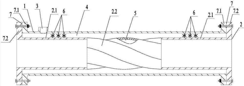
[0022] like figure 1 The shown pipe transporting mud device includes an outer pipe 1, an inner pipe 2 arranged concentrically with the outer pipe 1, and an air inlet 3 opened on the outer pipe 1. The gap between the outer pipe 1 and the inner pipe 2 is formed as a high-pressure gas. Channel 4, the air inlet 3 is communicated with the high pressure air channel 4, wherein, the wall thickness of the outer pipe 1 is the same as that of the inner pipe 2 and both are 5-7mm (preferably 6mm), and the height of the high-pressure air channel is 16-20mm (preferably 18mm); In addition, the edge of the two ends of the outer pipe 1 extends vertically outward with a circle of outer connecting disks 7.1, and the edge of both ends of the inner pipe 2 extends vertically outward with a circle of inner connecting disks 7.2, and the outer connecting disk 7....


PUM


Abstract

The invention discloses a pipeline mud conveying device. The pipeline mud conveying device comprises an outer pipeline, an inner pipeline concentric with the outer pipeline, and an air inlet formed in the outer pipeline, and a high-pressure air way is formed by a gap between the outer pipeline and the inner pipeline. A plurality of high-frequency vibrators are arranged in the high-pressure air way and located on the air inlet side. A high-pressure air hole communicating with the high-pressure air way is formed in the inner pipeline and located in the air inlet side. Each high-frequency vibrator comprises a pair of vibration supports, a vibrator shaft, a plurality of blades and a vibration steel ball arranged on the top of each blade through a vibration spring. The defects that during channel dredging work, the flowing resistance of mud in the pipelines is large, hydraulic power along the way is reduced rapidly, consequently, a dredger mud conveying system pipeline is abraded and blocked, the conveying distance is short and energy consumption is high are overcome, and therefore the flowing resistance of the mud in the pipelines is reduced, and hydraulic losses of mud along the way are reduced.

Description

technical field [0001] The invention belongs to the technical field of pipeline mud transportation, in particular to a pipeline mud transportation device. Background technique [0002] On the dredger for channel dredging, the dredging mud pump sucks up the cut mud, and transports the mud from the dredging point to the distant mud storage and processing point through the large-diameter and long-distance mud pipeline. Due to the characteristics of many components, high concentration and large flow rate of the dredged mud, the mud is in a multiphase flow state when it is transported in the pipeline, and its flow rate is disturbed greatly and the flow field is complex. This leads to the large flow resistance of the mud in the pipeline, and the rapid drop of hydraulic pressure along the route, which often leads to the wear, blockage, short conveying distance and high energy consumption of the pipeline of the dredger's mud conveying system. The limited dredging operation scope, d...

Claims


Application Information

Patent Timeline
Patent Type & Authority Applications(China)
IPC IPC(8): E02F7/10
CPCE02F7/10
Inventor 熊庭周栋彬张新卓张梦达
Owner WUHAN UNIV OF TECH
Why Eureka
Try Eureka