
Negative flow inlet and outlet separated combined control hydraulic system

A composite control and hydraulic system technology, which is applied to earth movers/excavators, construction, etc., can solve problems such as poor controllability and large throttling loss at the valve port, so as to reduce heat generation, reduce throttling loss, and improve operation speed effect

Active Publication Date: 2017-08-18
TAIYUAN UNIV OF TECH
View PDF7 Cites 15 Cited by
  • Summary
  • Abstract
  • Description
  • Claims
  • Application Information

AI Technical Summary

Problems solved by technology

[0004] Aiming at the deficiencies of the above-mentioned prior art, the present invention provides a negative flow inlet and outlet independent composite control hydraulic system, which effectively solves the problems of poor controllability and large throttling loss at the valve port in the existing negative flow system

Method used


Image

  • Negative flow inlet and outlet separated combined control hydraulic system
  • Negative flow inlet and outlet separated combined control hydraulic system

Examples


Embodiment Construction

[0023] The specific embodiments of the present invention will be further described below in conjunction with the accompanying drawings, but the embodiments of the present invention are not limited thereto.

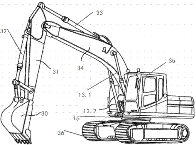
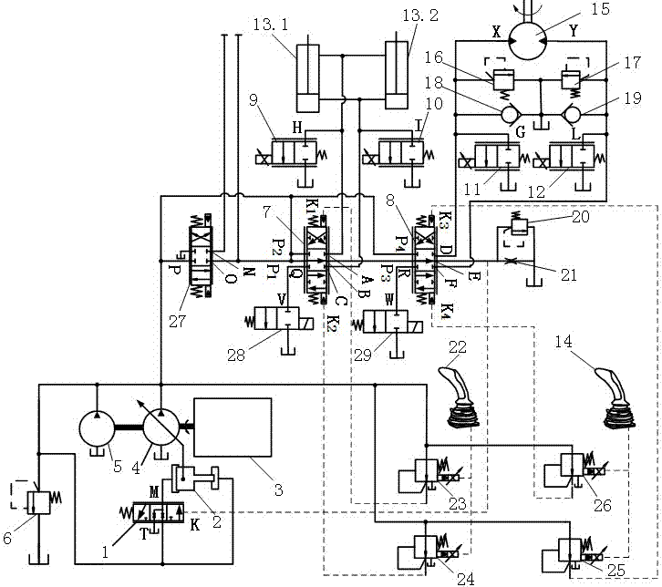
[0024] attached figure 2 Shows the specific structure of the preferred embodiment of the present invention, including the main pump control valve 1, the variable piston 2, the power source 3, the main pump 4, the pilot pump 5, the main circuit safety valve 6, the first main control multi-channel Valve 7, the second main control multi-way valve 8, the first proportional throttle valve 9, the second proportional throttle valve 10, the third proportional throttle valve 11, the fourth proportional throttle valve 12, the boom hydraulic cylinder 13, The second operating handle 14, the rotary hydraulic motor 15, the first rotary brake valve 16, the second rotary brake valve 17, the first one-way valve 18, the second one-way valve 19, the negative flow control circuit safety valv...


PUM


Abstract

A negative flow inlet and outlet separated combined control hydraulic system is additionally provided with four proportional throttle valves and two two-position two-way electromagnetic valves. The proportional throttle valves are additionally arranged in a movable arm hydraulic cylinder and a rotation hydraulic motor while displacement of a main pump is changed through negative flow control. When the main pump supplies oil to the movable arm hydraulic cylinder or the rotation hydraulic motor through a main control multi-path valve, the pressure or flow of the cavity to which the oil is supplied is controlled by the main control multi-path valve; the other of the movable arm hydraulic cylinder and the rotation hydraulic motor communicates with the proportional throttle valves, the pressure or flow thereof is controlled through movement of a valve element, and separated control over the pressure or flow of an oil inlet and an oil outlet is achieved. According to the negative flow inlet and outlet separated combined control hydraulic system, the throttling loss of a valve port is reduced, and the amount of system heating is reduced; and particularly under the overcharging situation, the throttling loss is remarkably reduced, the operation speed of a hydraulic actuator is improved, flow regeneration is achieved easily, and the effect is more remarkable.

Description

technical field [0001] The invention relates to a composite control system of a hydraulic excavator, in particular to an independent composite control system for an inlet and outlet of a hydraulic excavator. Background technique [0002] With the increasingly serious problems of energy shortage and environmental pollution, it is of great practical significance to study the energy consumption of construction machinery. As the most commonly used hydraulic engineering machinery, hydraulic excavators have always been the goal pursued by the industry to reduce energy consumption. With the development of hydraulic energy-saving technology, the hydraulic system of excavators has developed various control methods such as negative flow control, positive flow control and load sensitive control. Negative flow control means that the displacement of the hydraulic pump decreases as the control pressure signal increases, that is, the control pressure and displacement are inversely proport...

Claims


Application Information

Patent Timeline
Patent Type & Authority Applications(China)
IPC IPC(8): E02F9/22
CPCE02F9/22E02F9/2267
Inventor 权龙李会妨张晓刚黄家海
Owner TAIYUAN UNIV OF TECH
Learn More