Optical module high-and low-temperature test device

A technology for testing devices and optical modules, which is applied to measurement devices, optical instrument testing, and electrical devices, etc., can solve problems such as high price, inconvenient connection to the temperature probe of the module to be tested, and poor uniformity of temperature distribution on the surface of the optical module. , to achieve the effect of simple structure, avoiding inaccurate test data, and convenient installation and testing process

Pending Publication Date: 2017-08-18
SUZHOU YIRUI OPTOELECTRONICS TECH CO LTD
View PDF7 Cites 8 Cited by
  • Summary
  • Abstract
  • Description
  • Claims
  • Application Information

AI Technical Summary

Problems solved by technology

At present, a thermostat or a jet box with a glass cover interface is usually used as a temperature control source for high and low temperature tests, but the former has low efficiency, slow heating speed, and is prone to errors. The latter is expensive, and the size of the glass cover will limit the optical module test. The design size of the tooling board, especially the high-speed line of the high-speed optical module has wiring requirements, and the size limit of the glass cover will affect the wiring
And both are inconvenient in terms of connecting the temperature probe of the module under test
If manual pasting or placement is used, the change of the probe position will introduce more measurement data errors
Moreover, the air outlet of the glass cover is generally fixed, so that the flow of the airflow is relatively fixed. For the optical module with a large test volume, the temperature distribution uniformity on the surface of the optical module will not be good.

Method used


Image

  • Optical module high-and low-temperature test device
  • Optical module high-and low-temperature test device
  • Optical module high-and low-temperature test device

Examples


Embodiment Construction

[0023] The specific implementation manners of the present invention will be further described in detail below in conjunction with the accompanying drawings and embodiments. The following examples are used to illustrate the present invention, but are not intended to limit the scope of the present invention.

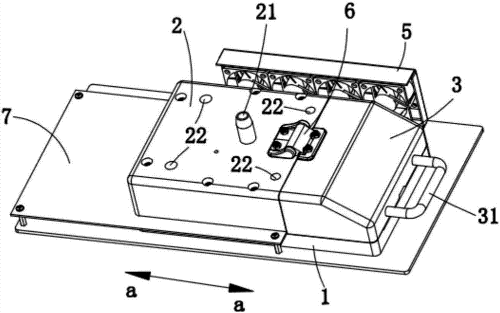
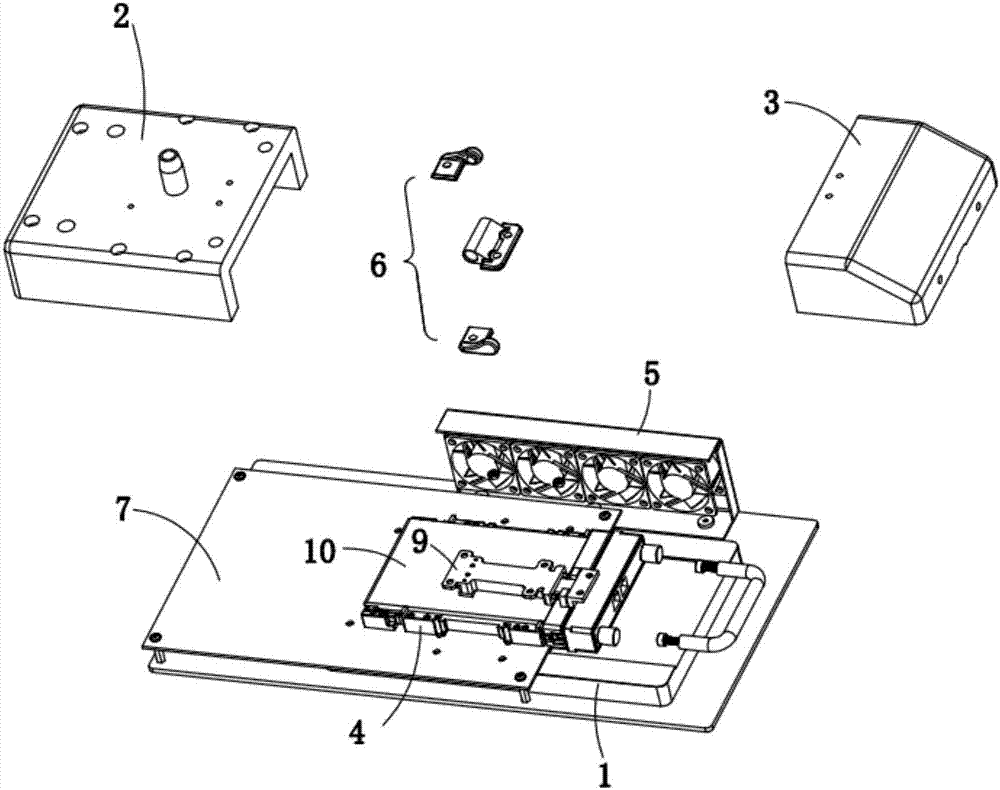
[0024] See figure 1 and figure 2 and Figure 4 , an optical module high and low temperature test device shown in a preferred embodiment of the present invention is used to test the optical module 10, the optical module high and low temperature test device includes a base, a housing 2 arranged on the base 1, a movable A reversible bin door 3 installed on the casing 2 , a test frame 4 arranged on the base 1 , and a heat dissipation assembly 5 arranged on one side of the casing 2 . The casing 2 is surrounded by a test cavity (not labeled), and the test rack 4 is arranged in the test cavity. In order to prevent water vapor from condensing due to excessive temperature diff...


PUM

PropertyMeasurementUnit
sizeaaaaaaaaaa

Abstract

The present invention relates to an optical module high-and low-temperature test device. The optical module high-and low-temperature test device is used for testing an optical module. The optical module high-and low-temperature test device comprises a base and a test frame arranged on the base; the optical module is arranged on the test frame; a thermocouple probe is arranged above the test frame; the thermocouple probe contacts with the optical module arranged on the test frame; and the thermocouple probe is fixed through a support. According to the optical module high-and low-temperature test device, the thermocouple probe is fixed through the support, and therefore, after the optical module is fixed on the test frame, the thermocouple probe can directly contact with the optical module, and thus, installation and testing techniques are convenient; the thermocouple probe does not move, so that the problem of inaccurate test data caused by the change of the displacement of the thermocouple probe can be avoided. Compared with the prior art, the optical module high-and low-temperature test device is simple in structure.

Description

technical field [0001] The invention relates to a high and low temperature testing device for an optical module. Background technique [0002] At present, in the production of high-speed optical transceiver modules for long-distance transmission, it is necessary to calibrate the parameters of optical modules at high and low temperatures to ensure the stability of wavelength and optical power. At present, a thermostat or a jet box with a glass cover interface is usually used as a temperature control source for high and low temperature testing, but the former has low efficiency, slow heating speed, and is prone to errors. The latter is expensive, and the size of the glass cover will limit the optical module test. The design size of the tooling board, especially the high-speed line of the high-speed optical module has wiring requirements, and the size limit of the glass cover will affect the wiring. And both are inconvenient in terms of connecting the temperature probe of the ...

Claims


Application Information

Patent Timeline
Patent Type & Authority Applications(China)
IPC IPC(8): G01M11/00G01K1/14G01K7/02
CPCG01K1/14G01K7/02G01M11/00Y02E10/50
Inventor 许乐
Owner SUZHOU YIRUI OPTOELECTRONICS TECH CO LTD
Why Eureka
Try Eureka