Local aluminium surface-back-field solar cell and preparation method of the same

A solar cell and aluminum back field technology, applied in the field of solar cells, can solve the problem of reducing the void rate of local aluminum back field cells, and achieve the effects of improving photoelectric conversion efficiency and solving the problem of black spots and black lines.

Pending Publication Date: 2017-08-18
JA SOLAR TECH YANGZHOU +1
View PDF6 Cites 12 Cited by
  • Summary
  • Abstract
  • Description
  • Claims
  • Application Information

AI Technical Summary

Problems solved by technology

[0007] The first object of the present invention is to provide a partial aluminum back field solar cell, which can greatly reduce the void ratio of the local aluminum back field cell by optimizing the process of aluminum paste printing and sintering, thereby solving the problem of It solves the problem of black dots and black lines during electroluminescence, and improves the photoelectric conversion efficiency of the battery

Method used


Image

  • Local aluminium surface-back-field solar cell and preparation method of the same
  • Local aluminium surface-back-field solar cell and preparation method of the same
  • Local aluminium surface-back-field solar cell and preparation method of the same

Examples


Embodiment 1

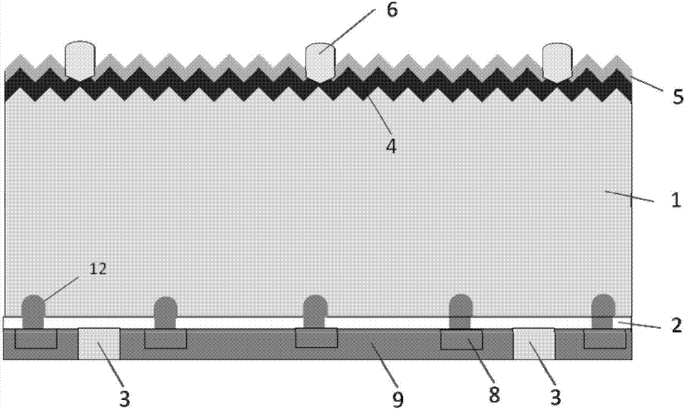
[0036] Such as figure 1 As shown, the local aluminum back field solar cell provided in this embodiment comprises a crystalline silicon wafer 1, a passivation layer 2 and a back electrode 3 are provided on the back side of the crystalline silicon wafer, an emitter 4, an anti-reflection layer 5 and the front electrode 6, the passivation layer 2 on the back of the crystalline silicon wafer is provided with a laser slot 71, and the laser slot 71 is provided with a first layer of partial back aluminum paste 8 covering the slot 71, wherein the first layer The partial back aluminum paste 8 is formed by co-sintering with the front electrode 6 and the back electrode 3 , and the second layer of high temperature treated back aluminum paste 9 is provided on the first layer of partial back aluminum paste 8 .

[0037] The second layer of back aluminum paste 9 is directly or indirectly electrically connected to the back electrode 3 and the first partial back aluminum paste 8 .

[0038] The ...

Embodiment 2

[0059] The difference from Example 1 is that the aluminum paste on the back of the second layer adopts hollow printed patterns, and the area of ​​the aluminum paste accounts for 30% of the total area of ​​the battery.

Embodiment 3

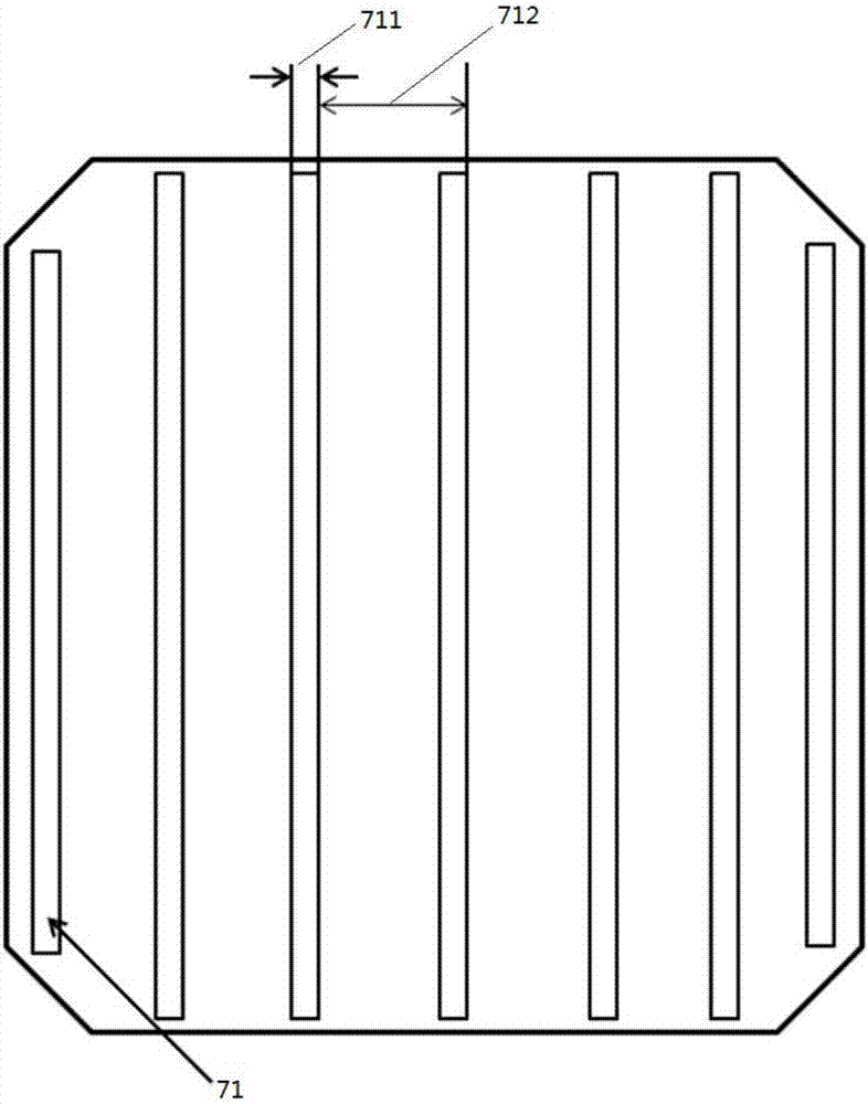
[0061] The difference from Example 1 is that here the laser adopts the method of opening holes, such as image 3 , the opening diameter 721 is 200 μm, and the hole spacing 722 is 700 μm. The first layer of aluminum paste is also arranged in the same way as the laser holes, and the diameter is slightly larger than the opening diameter, which is 300 μm. The second layer of aluminum paste is printed on the whole surface. The place of the back electrode is not printed.


PUM

PropertyMeasurementUnit
thicknessaaaaaaaaaa
thicknessaaaaaaaaaa
widthaaaaaaaaaa

Abstract

The invention discloses a local aluminium surface-back-field solar cell. The local aluminium surface-back-field solar cell includes a crystalline silicon wafer, wherein the back surface of the crystalline silicon wafer is provided with a passivation layer and a back electrode; and the front surface of the crystalline silicon wafer is provided with an emitting electrode, an anti-reflection layer and a front electrode. The local aluminium surface-back-field solar cell is characterized in that a laser open hole or open groove is formed in the passivation layer on the back surface of the crystalline silicon wafer; the laser open hole or open groove is provided with a first layer of local back surface aluminium paste covering the laser open hole or open groove; the first layer of local back surface aluminium paste, the front electrode and the back electrode are formed together through sintering; and a second layer of back surface aluminium paste which processed through high temperature is arranged on the first layer of local back surface aluminium paste. The local aluminium surface-back-field solar cell can greatly reduce the voidage of the local aluminium surface-back-field cell through optimization of aluminium paste printing and the sintering technology so as to solve the problem that black points and black lines appear during the electroluminescent process and improve the photoelectric conversion efficiency of the cell. The invention also discloses a preparation method of the local aluminium surface-back-field solar cell.

Description

technical field [0001] The invention belongs to the field of solar cells, and in particular relates to a partial aluminum back field solar cell and a preparation method thereof. Background technique [0002] Photovoltaic technology is a technology that uses large-area p-n junction diodes to convert solar energy into electrical energy. This p-n junction diode is called a solar cell. The semiconductor materials used to make solar cells have a certain band gap. When the solar cell is irradiated by the sun, photons with energy exceeding the band gap generate electron-hole pairs in the solar cell. The p-n junction separates the electron-hole pairs, and the p-n junction The asymmetry determines the flow direction of different types of photo-generated carriers, and the external power can be output through the external circuit connection. This is similar to the principle of ordinary electrochemical cells. [0003] Industrial production of p-type crystalline silicon solar cells us...

Claims


Application Information

Patent Timeline
Patent Type & Authority Applications(China)
IPC IPC(8): H01L31/0224H01L31/18
CPCH01L31/022425H01L31/18H01L31/186Y02E10/50Y02P70/50
Inventor 蒋秀林吴兰峰周艳方张峰单伟
Owner JA SOLAR TECH YANGZHOU
Why Eureka
Try Eureka