Device and method for recycling spray cooling cutting fluid

A technology of spray cooling and cutting fluid, applied in metal processing equipment, cleaning methods and utensils, chemical instruments and methods, etc., can solve the problems of manpower and material resources, increased processing costs, waste of resources, etc. achieve simple effects

Inactive Publication Date: 2017-08-22
CHANGZHOU UNIV
View PDF7 Cites 16 Cited by
  • Summary
  • Abstract
  • Description
  • Claims
  • Application Information

AI Technical Summary

Problems solved by technology

In this way, a large amount of waste cutting working fluid will be formed, which will not only greatly increase the processing cost and cause waste of resources, but also cost manpower and material resources to process the waste working fluid

Method used


Image

  • Device and method for recycling spray cooling cutting fluid

Examples


Embodiment Construction

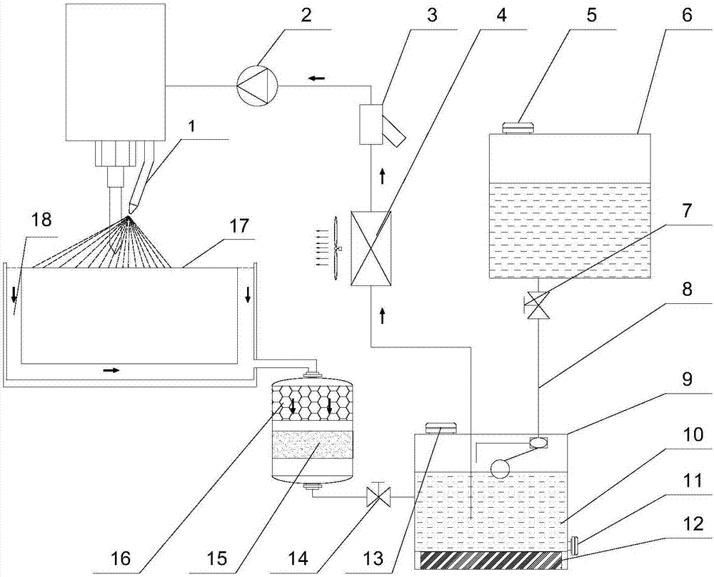
[0011] Such as figure 1 As shown, a kind of equipment and method for recycling working fluid of the present invention comprises an atomizing nozzle (1), a high-pressure water pump (2), a Y-type filter (3), an air-cooled cooler (4), and a liquid replenishing Port (5), replenishment tank (6), stop valve 1 (7), float valve (8), liquid storage tank (9), recovery fluid (10), sewage outlet (11), magnet (12), cleaning port (13), cut-off valve 2 (14), secondary filter (15), primary filter (16), stand (17), cutting fluid recovery channel (18) forms.

[0012] The specific implementation process is:

[0013] When the system starts to work, the cutting fluid is pumped out from the liquid storage tank (9) by the high-pressure water pump (2). The cutting fluid first passes through the air-cooled cooler (4) to cool down, and then passes through the Y-type filter (3) to remove impurities. Filter, and then flow to the atomizing nozzle (1) through the pressurized pressure of the high-pressure...


PUM


Abstract

The object of the present invention is to provide a recycling equipment and method for spray cooling cutting fluid, which is characterized in that it consists of a liquid supply system, a recovery system, a liquid replenishment system, a liquid storage tank and a stand. Specific components include atomizing nozzle (1), high-pressure water pump (2), Y-type filter (3), air-cooled cooler (4), liquid replenishment port (5), liquid replenishment tank (6), and shut-off valve 1 (7) , float valve (8), liquid storage tank (9), recovery liquid (10), sewage outlet (11), magnet (12), cleaning port (13), shut-off valve 2 (14), secondary filter (15 ), primary filter (16), stand (17), cutting fluid recovery channel (18). Compared with the existing cutting workbench, it can realize the recycling of cutting fluid, and has the advantages of long working fluid replacement period, convenient installation and use, and automatic fluid replenishment.

Description

technical field [0001] The invention relates to a device and method for recycling spray cooling cutting fluid, and belongs to the field of cooling fluid recycling. Background technique [0002] In metal cutting processing, the working fluid has a great influence on the process index. Only by ensuring the insulation performance, cleaning performance and cooling performance of the working fluid can it be guaranteed that it will have a positive impact on the cutting speed, surface roughness and machining accuracy of the product. However, during the use of the cutting fluid, a large amount of fine chips, dust and other impurities will be mixed in, resulting in a decrease in cutting performance. Due to the lack of effective recycling devices, the machining performance is often stabilized by constantly replacing fresh cutting fluid during the cutting process of machine tools. In this way, a large amount of waste cutting working fluid will be formed, which not only greatly increas...

Claims


Application Information

Patent Timeline
Patent Type & Authority Applications(China)
IPC IPC(8): B03C1/30B23Q11/00B08B9/08
CPCB03C1/30B08B9/08B23Q11/00
Inventor 周年勇王露曹玉春陈海飞
Owner CHANGZHOU UNIV
Why Eureka
Try Eureka