Boundary layer effect channel pushing engine for equipment

A boundary layer and engine technology, which is applied in the direction of machines/engines, ramjet engines, mechanical equipment, etc., can solve the problems of high difficulty in manufacturing the turntable structure, small output torque of the turbine, and obstruction of gas thrust, so as to improve fuel consumption. Economical, high utilization efficiency, and small effect resistance

Inactive Publication Date: 2017-08-22
刘国利
View PDF0 Cites 2 Cited by
  • Summary
  • Abstract
  • Description
  • Claims
  • Application Information

AI Technical Summary

Problems solved by technology

[0004] At present, most of the rotary engines used are rotating according to the cosine law, the thrust of the gas is greatly hindered, and the exhaust waste heat is seriously wasted; the blade-type gas turbines and steam turbines rely on the impact of the airflow to the blades to generate an impeller along the direction of rotation of the impeller. The component force rotates, and the other component force is the thrust along the axial direction to strengthen the useless work of the bearing friction, so that the output torque of the turbine is not large. At the same time, the turbine must meet the gas parameters to be efficient. The gas that is less than the parameter can only escape from the blades. Running away, the high-temperature and high-pressure airflow has a great impact on the blades, and at the same time, the temperature resistance of the blades is a problem, which requires extremely harsh manufacturing materials! The most important problem is that the fluid has a thin layer of adsorption on the blades to generate viscous force, which is an impeding force opposite to the direction of impeller rotation, which means that the impeller must consume kinetic energy to overcome the viscous force. The Tesla turntable is The viscous force of the boundary layer effect in the narrow gap is used to drive the turntable to rotate at high speed, but the structure of the turntable is difficult to manufacture. The biggest problem is that when the load is heavy, the fluid directly approaches the radial direction, and the torque generated is very small!

Method used


Image

  • Boundary layer effect channel pushing engine for equipment
  • Boundary layer effect channel pushing engine for equipment
  • Boundary layer effect channel pushing engine for equipment

Examples


Embodiment Construction

[0050] Preferred embodiments of the present invention will be described in detail below in conjunction with the accompanying drawings.

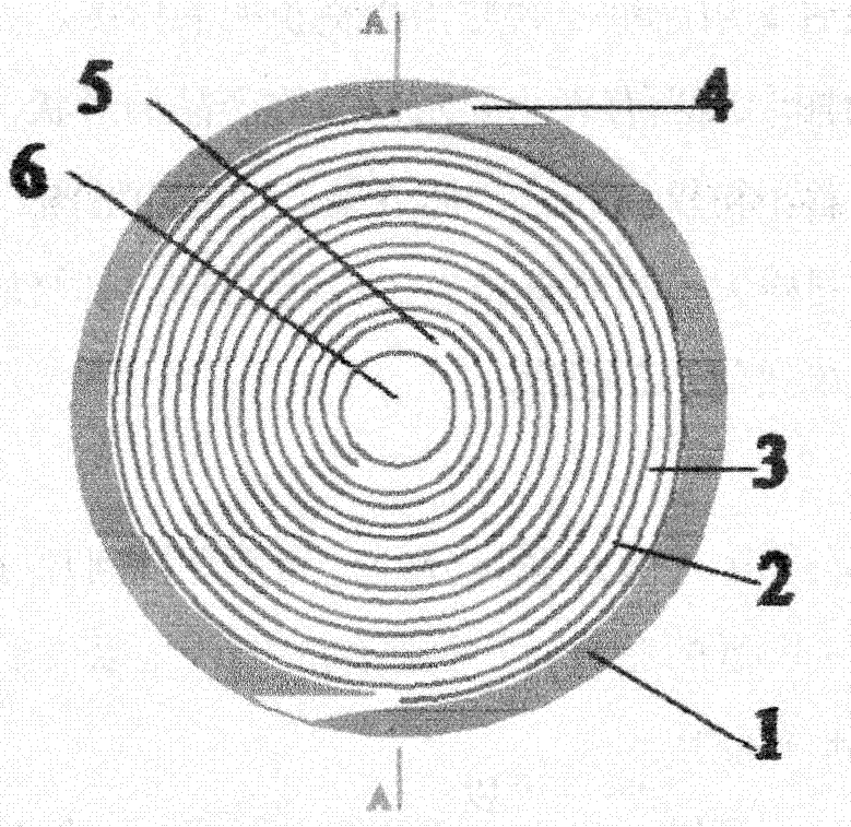
[0051] see figure 1 As shown in the embodiment therein, in the rotor formed by the boundary layer effect channel 3 of the two-headed helix 2 in the circular housing 1, the fluid enters through the air inlet 4 and flows through the boundary layer effect channel to generate shear. The shearing force pushes the rotor to rotate, and the fluid is finally discharged from the exhaust port of the channel, and the power output shaft position 6 in the center is provided with a power output shaft.

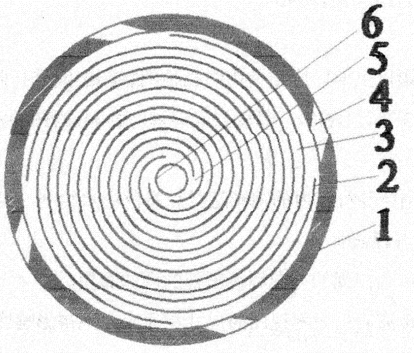
[0052] join figure 2 Among them, the rotor is composed of four helical bodies 2, the air consumption and output torque are increased, and the helical body 2 can be provided with a multi-head structure.

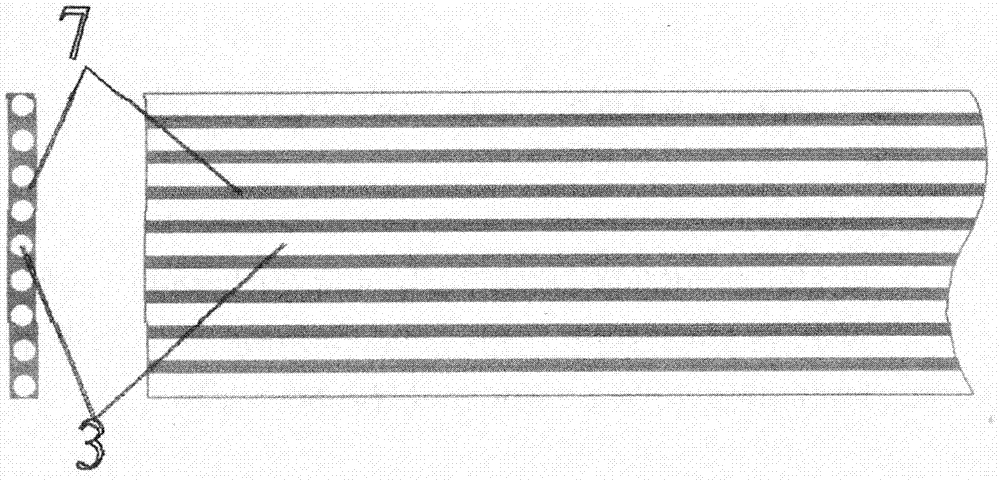
[0053] image 3 , Figure 4 , Figure 5 , Figure 24 As shown, a plurality of narrow tubes or corrugated tubes with boundary layer effect channels ar...


PUM


Abstract

The invention discloses a boundary layer effect channel propulsion engine for equipment, aiming to provide a motor capable of outputting high torque to replace current equipment vehicles, tanks, helicopters, ships and steam turbines, and mainly to realize equipment for fighter jets and missiles. scramjet engine. Its technical points are as follows: it includes a scramjet engine for equipped fighters and missiles consisting of a gas-propelled boundary layer effect channel rotor engine, a ramjet engine, and an air intake shroud. The described boundary layer effect channel rotor engine includes a boundary layer effect channel The rotor turbine is composed of multiple vortex-helical elongated channels and vortex-helical multi-layer superimposition. The rotor turbine is equipped with multiple superconducting heat pipes to cool and dissipate the turbine. The flame holder flame tube of the combustion chamber is distributed with multiple inclined inlets. The air channel constitutes the vortex flow combustion, and the ramjet engine includes a boundary layer effect channel rotor engine connected to drive a turbofan compressor, an inner and outer bypass, a combustion chamber, and the like.

Description

[0001] Technical field: [0002] The invention relates to an engine, in particular to a rotor engine for equipment such as fighter planes and missiles. [0003] Background technique: [0004] At present, most of the rotary engines used are rotating according to the cosine law, the thrust of the gas is greatly hindered, and the waste heat of the exhaust gas is seriously wasted; the blade-type gas turbine and steam turbine rely on the impact of the airflow to the blade to generate a rotation direction along the impeller. The component force rotates, and the other component force is the thrust along the axial direction to strengthen the useless work of the bearing friction, so that the output torque of the turbine is not large. At the same time, the turbine must meet the gas parameters to be efficient. The gas that is less than the parameter can only escape from the blades. Running away, the high-temperature and high-pressure airflow has a great impact on the blades, and at the sa...

Claims


Application Information

Patent Timeline
Patent Type & Authority Applications(China)
IPC IPC(8): F02K7/10F02C7/042
CPCF02K7/10F02C7/042
Inventor 不公告发明人
Owner 刘国利
Why Eureka
Try Eureka