
Biomass boiler

A biomass boiler and furnace body technology, applied in the direction of combustion methods, lighting and heating equipment, indirect carbon dioxide emission reduction, etc., can solve the problems of poor fluidity, unfavorable feeding, heat pollution of the surrounding environment, increased production costs, etc., to achieve good control, Low maintenance and operation cost, full combustion effect

Inactive Publication Date: 2017-08-29
ANHUI DING BEAM BIO ENERGY TECH DEV CO LTD
View PDF5 Cites 6 Cited by
  • Summary
  • Abstract
  • Description
  • Claims
  • Application Information

AI Technical Summary

Problems solved by technology

However, the feeding device of the traditional biomass boiler can only use biomass particles as fuel. For the strip-shaped wood block and straw fuel with large shape and volume, the existing feeding device cannot It is directly sent to the combustion chamber of the boiler for combustion, and it must be crushed, refined, formed and other processing procedures, which will increase production costs and reduce work efficiency
[0003] At the same time, the thermal efficiency of biomass boilers is only about 80%, and the energy utilization rate is low. At the same time, the exhaust gas temperature of existing biomass boilers is generally 180 ° C ~ 150 ° C, and this part of the flue gas energy can account for 7 ~ 7% of the total energy of the boiler fuel. 9%, this part of the heat energy of the flue gas is discharged into the atmosphere, causing a great waste of energy, and also causing heat pollution to the surrounding environment

Method used


Image

  • Biomass boiler
  • Biomass boiler
  • Biomass boiler

Examples


Embodiment 1

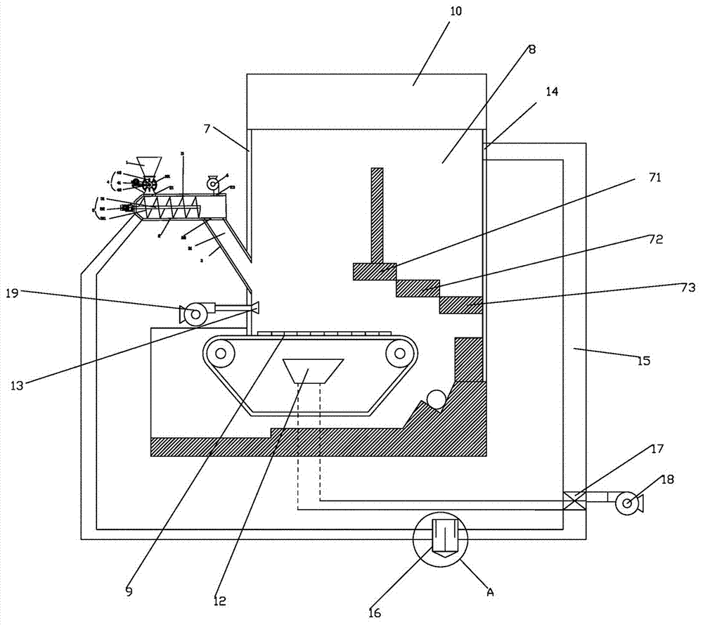
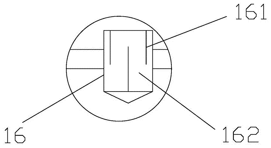
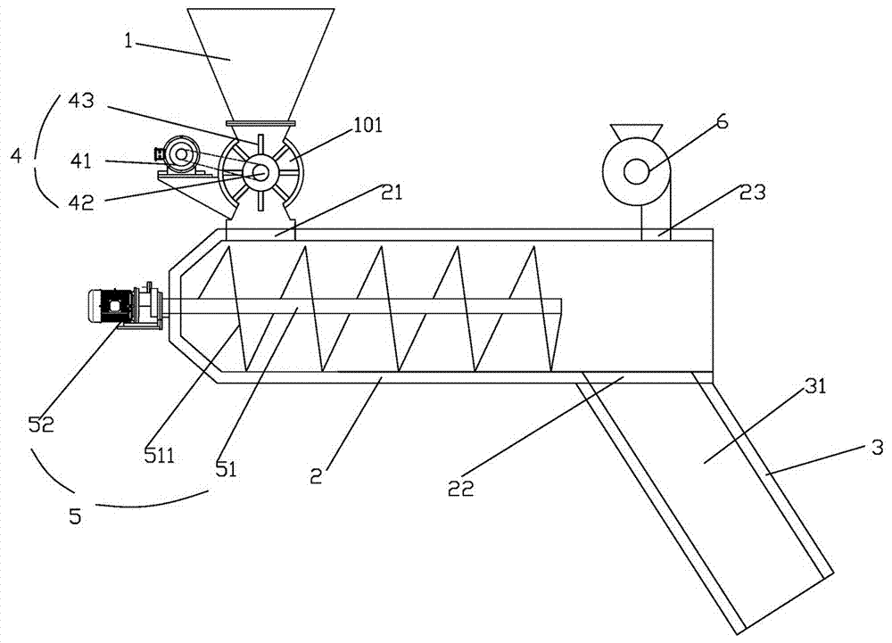
[0030] Example 1: Reference figure 1 , figure 2 as well as image 3 , a biomass boiler, comprising a furnace body 7, a combustion chamber 8 arranged inside the furnace body 7, a moving grate 9 arranged at the bottom of the combustion chamber 8, a feeding device 11 arranged at the moving grate 9, a The drum 10 above the chamber 8, the first air inlet chamber 12 arranged below the moving grate 9, the second air inlet chamber 13 arranged between the discharge port of the feeding device 11 and the moving fire grate, and the second air inlet chamber 13 arranged in the combustion chamber The smoke outlet 14 on the chamber 8, the smoke outlet 14 is connected with a flue gas pipe 15, the other end of the flue gas pipe 15 is connected to the inlet of the dust collector 16, and the outlet of the dust collector 16 is connected to the feeding device 11 through a pipeline To dry the material, the flue gas pipeline 15 is provided with an air preheater 17 that uses the flue gas in the pip...


PUM


Abstract

The invention relates to the technical field of biomass boilers, and particularly relates to a biomass boiler. The biomass boiler comprises a boiler body, a combustion chamber, a moving grate, a feeding device, a boiler barrel, a first air inlet chamber, a second air inlet chamber and a smoke outlet, wherein the combustion chamber is arranged in the boiler body, the moving grate is arranged at the bottom of the combustion chamber, the feeding device is arranged at the moving grate, the boiler barrel is arranged above the combustion chamber, the first air inlet chamber is arranged below the moving grate, the second air inlet chamber is arranged below a discharge port of the feeding device, and the smoke outlet is formed in the combustion chamber. The biomass boiler has the advantage of simple structure, and the feeding quantity can be adjusted at any time, so that the feeding quantity of materials is kept uniform and consistent, the boiler combustion level is consistent, the boiler combustion stability is increased, and the utilization rate of energy is effectively increased; additionally, the biomass boiler has an ideal dust removal effect, the energy is recycled, and the cost is reduced.

Description

technical field [0001] The invention relates to the technical field of biomass boilers, in particular to a biomass boiler. Background technique [0002] Biomass boiler is a type of boiler, which has the advantages of multi-purpose boiler, strong conversion system, low installation cost, safety and environmental protection. However, the feeding device of the traditional biomass boiler can only use biomass particles as fuel. For the strip-shaped wood block and straw fuel with large shape and volume, its poor fluidity is not conducive to feeding, and the existing feeding device cannot If it is directly sent to the combustion chamber of the boiler for combustion, it must be crushed, refined, formed and other processing procedures, which will increase production costs and reduce work efficiency. [0003] At the same time, the thermal efficiency of biomass boilers is only about 80%, and the energy utilization rate is low. At the same time, the exhaust gas temperature of existing ...

Claims


Application Information

Patent Timeline
Patent Type & Authority Applications(China)
IPC IPC(8): F23B40/00F23K3/16F23L1/02F23L9/02F23L15/00F23J15/02
CPCF23B40/00F23B2700/012F23J15/02F23J2217/60F23K3/16F23L1/02F23L9/02F23L15/00Y02E20/34
Inventor 梁念喜阮景波朱华徐祖成宫文伟
Owner ANHUI DING BEAM BIO ENERGY TECH DEV CO LTD
Learn More