Quantitative measurement and characterization method of abrasive wear of micropowder diamond grinding wheel

A diamond grinding wheel and grinding wheel surface technology, which is applied in the field of ultra-precision machining of large-diameter optical components, can solve the problems of high cost investment, high cleanliness and vibration isolation requirements, and the inability to realize the in-situ detection of grinding wheel wear and tear, and achieve hardware cost investment The effect of reducing and avoiding measurement errors

Active Publication Date: 2020-04-14
LASER FUSION RES CENT CHINA ACAD OF ENG PHYSICS
View PDF6 Cites 0 Cited by
  • Summary
  • Abstract
  • Description
  • Claims
  • Application Information

AI Technical Summary

Problems solved by technology

For the micropowder diamond grinding wheel in the field of optical processing, it is necessary to quantitatively measure and characterize the abrasion and wear of ultrafine diamond particles, which is convenient for real-time evaluation of the processing ability of the grinding wheel. The cost of equipment is large, and the use environment needs to have high cleanliness and vibration isolation requirements, so it is impossible to realize the on-site detection of grinding wheel wear and tear

Method used


Image

  • Quantitative measurement and characterization method of abrasive wear of micropowder diamond grinding wheel
  • Quantitative measurement and characterization method of abrasive wear of micropowder diamond grinding wheel
  • Quantitative measurement and characterization method of abrasive wear of micropowder diamond grinding wheel

Examples


Embodiment

[0039] The object of measurement and characterization is 1800# resin bonded diamond grinding wheel, the diameter of diamond particles is 8μm-12μm. Install the diamond grinding wheel on the spindle of the ultra-precision grinding machine, and use the grinding wheel in-situ dresser for precision modification and grinding of optical components. The quantitative measurement and characterization method of micropowder diamond grinding wheel abrasive wear in this embodiment includes the following steps:

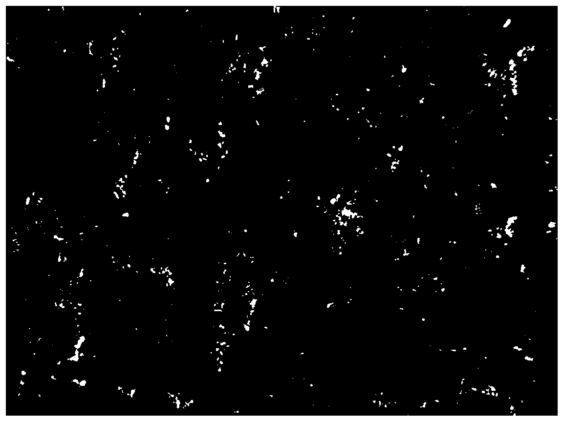
[0040] 1) Install the high-magnification microscope on the machine tool table, and observe the surface of the grinding wheel with the lens barrel vertically upward. After adjusting the focal length until the microscopic appearance of the grinding wheel is clear, take pictures to obtain the microscopic image of the worn surface of the grinding wheel, as shown in figure 1 shown;

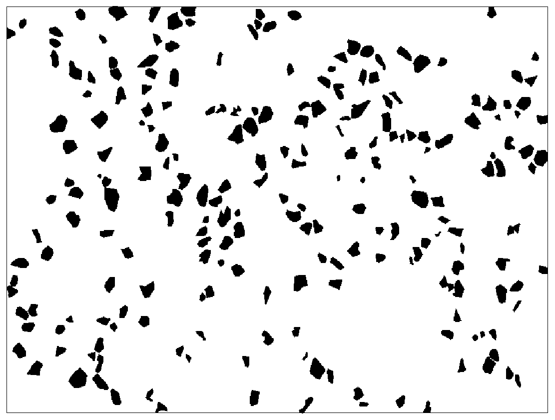
[0041] 2) The computer reads the microscopic image of the surface of the grinding wheel to obtain the im...


PUM

PropertyMeasurementUnit
particle diameteraaaaaaaaaa

Abstract

The invention provides a micro powder diamond grinding wheel abrasive particle abrasion quantitative measurement representation method. The method comprises the following steps: 1) obtaining the micro-topographies of different positions on the surface of a grinding wheel in an abrasion state; 2) obtaining an image RGB matrix; 3) removing glitch noise in the image; 4) performing image enhancement by using differential operation; 5) extracting an area corresponding to the abrasive particles in the image; 6) binarizing the whole image; 7) obtaining the number of the abrasive particles and the projected area data of the abrasive particles; 8 ) dividing the number of the abrasive particles by the total area of an micro-topography image to obtain the abrasive particles distribution density; and 9) calculating average abrasion area of the projected area data of the abrasive particles according to normal distribution. The method uses noncontact measurement, avoids a measurement error caused by probe abrasion during contact measurement, extracts the number of an abrasive particle abrasive plane and projected area information, and quantitatively represents the different abrasion state of the grinding wheel.

Description

technical field [0001] The invention relates to the field of ultra-precision machining of large-diameter optical elements, in particular to a quantitative measurement and characterization method for abrasive wear of a micropowder diamond grinding wheel in the ultra-precision grinding process of optical elements. Background technique [0002] In large-scale high-precision optical systems such as high-power laser devices and astronomical telescopes, a large number of large-caliber high-precision optical components are used, including planar optical components, spherical optical components, and aspheric optical components. The high-efficiency and high-precision forming processing methods of large-diameter optical components mainly include milling and ultra-precision grinding forming, etc. The processing tools used are superhard micro-powder diamond grinding wheels with a particle size of less than 10 μm. During the processing, with the continuous accumulation of material remova...

Claims


Application Information

Patent Timeline
Patent Type & Authority Patents(China)
IPC IPC(8): G06T5/00G06T7/13G06T7/136
CPCG06T5/002G06T7/13G06T2207/10061
Inventor 周炼安晨辉赵世杰陈贤华廖德锋张清华王健许乔
Owner LASER FUSION RES CENT CHINA ACAD OF ENG PHYSICS
Why Eureka
Try Eureka