Dual-polarization tight coupling dipole array antenna

A dual-polarized antenna, array antenna technology, applied to antenna unit combinations, antennas, resonant antennas and other directions with different polarization directions, can solve the problems of large radius, affecting array performance, difficult to achieve miniaturization, easy to conform, etc. To achieve the effect of easy processing, good technical foresight, and good technical foresight

Pending Publication Date: 2017-08-29
NANJING UNIV OF AERONAUTICS & ASTRONAUTICS
View PDF6 Cites 24 Cited by
  • Summary
  • Abstract
  • Description
  • Claims
  • Application Information

AI Technical Summary

Problems solved by technology

Since the elements of an array antenna are often arranged closely, there will be strong coupling between adjacent elements, which makes the field distribution of the array element different from that of a single UWB antenna, thereby affecting the performance of the entire array.
In addition to the coupling problem, the volume problem of UWB antennas has also been criticized. Traditional Vivaldi antenna

Method used


Image

  • Dual-polarization tight coupling dipole array antenna
  • Dual-polarization tight coupling dipole array antenna
  • Dual-polarization tight coupling dipole array antenna

Examples


Embodiment Construction

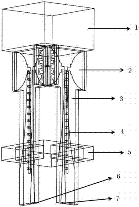
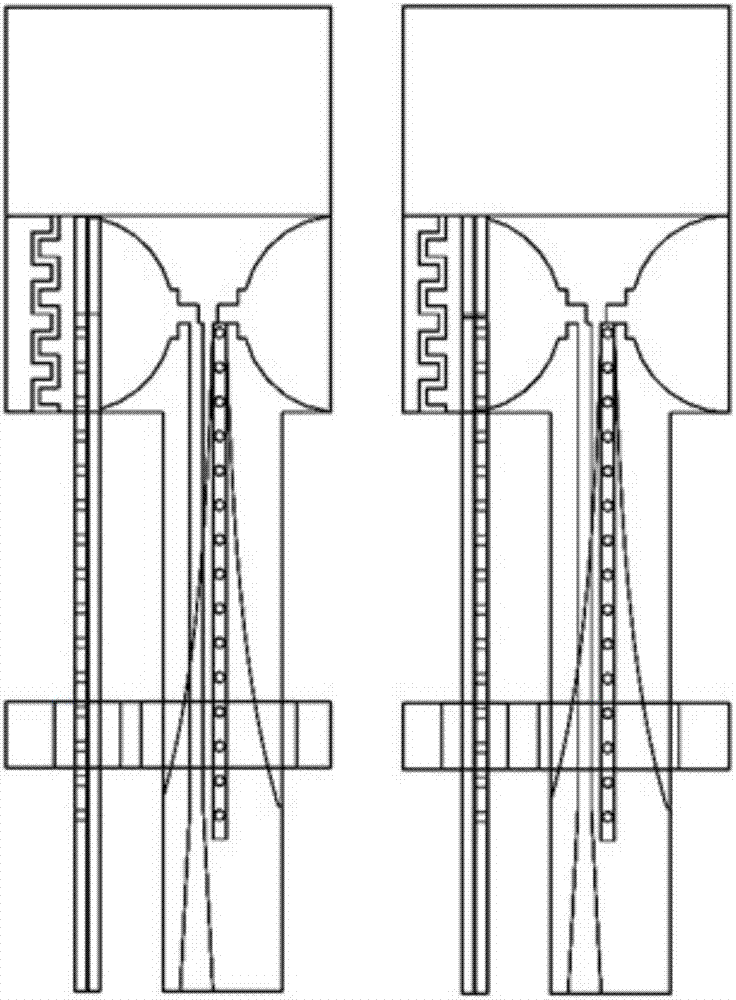
[0031] The dual-polarized antenna unit is composed of orthogonally placed single-polarized dipole units, and the single-polarized dipole unit includes a wide-angle matching layer 1, a dipole unit 2 on a dielectric substrate, a dielectric substrate 3, a transition bar Lun 4, metal ground 5, port one 6 and feed port two 7 fed by the coaxial line; the half-wave dipole unit includes two monopoles on the left and right, and each monopole includes a dipole arm and the interdigitated section; the left and right dipole arms of the dipole unit are respectively semicircular with openings to the left and openings to the right, and the semicircular openings are connected to the interdigitated section; the adjacent dipole units The interdigitated sections are complementary inserted to form a coupling (the dipole impedance is related to its shape, and the shape can be fine-tuned to make the impedance reach the expected set value); the feed balun is composed of the bottom triangular tapered m...


PUM


Abstract

The invention discloses a dual-polarization tight coupling dipole array antenna. An antenna unit is formed by orthogonally combining two single-polarization dipole units of a same type. Each single-polarization dipole unit is formed by an interdigital dipole, feed line Balun, metal floor and a wide angle matching layer. The feed line Balun is formed by three portions: a coplanar strip line portion connected to the dipole, a gradual change triangle microstrip transmission line whose feed end is connected to a coaxial line and an intermediate transition portion. In the invention, based on the dipole array antenna, a mutual-coupling effect among array elements is used to expand a frequency bandwidth, and the wide angle matching layer is introduced to improve a wide angle scanning characteristic of an antenna array. A common mode resonance caused by a common mode current existing at a specific frequency point under coplanar strip line feed is processed. Through arranging a 50ohm resistor between the metal floor and gradual change ground, the common mode current is shunted so that the common mode resonance disappears, simultaneously a work bandwidth of an antenna is expanded and performance in a whole work bandwidth can be well increased.

Description

technical field [0001] The present invention relates to the technical field of ultra-wideband antennas, in particular to a dual-polarized ultra-wide bandwidth angle antenna array based on interdigitated tightly coupled dipole units. Background technique [0002] Traditional ultra-wideband array antennas have been developed rapidly because of their advantages, but with the deepening of research, their shortcomings have gradually emerged. The first, and most important constraint, is the effect of inter-array coupling on performance. Since the elements of an array antenna are often arranged closely, there will be strong coupling between adjacent elements, which makes the field distribution of the array element different from that of a single UWB antenna, thereby affecting the performance of the entire array. In addition to the coupling problem, the volume problem of UWB antennas has also been criticized. Traditional Vivaldi antenna arrays and ridged gradient slot antenna array...

Claims


Application Information

Patent Timeline
IPC IPC(8): H01Q1/38H01Q1/50H01Q9/16H01Q21/00H01Q21/24
CPCH01Q1/38H01Q1/50H01Q9/16H01Q21/00H01Q21/0006H01Q21/0075H01Q21/24
Inventor 朱俊杰郭莹李雪
Owner NANJING UNIV OF AERONAUTICS & ASTRONAUTICS
Why Eureka
Try Eureka