Inverter control device and control device for vehicle
A technology of control devices and inverters, which is applied in the direction of power consumption devices, control systems, vehicle energy storage, etc., and can solve problems such as DC link voltage rise, DC power supply damage, damage, etc.
- Summary
- Abstract
- Description
- Claims
- Application Information
AI Technical Summary
Problems solved by technology
Method used
Image

Examples
no. 1 approach
[0040] Next, the inverter control device according to the first embodiment will be described based on the drawings. Such as figure 1 As shown, the inverter control device 20 takes the rotating electric machine driving device 1 including the inverter 10 as a control object, and drives and controls the rotating electric machine 80 via the rotating electric machine driving device 1 . The inverter control device 20 performs switching control of the switching elements 3 constituting the inverter 10 , and executes failsafe control described later when a failure occurs in the rotary electric machine drive device 1 .
[0041] The inverter 10 is connected to the high-voltage battery 11 (DC power supply) via the contactor 9 (power switch) and connected to the AC rotating electrical machine 80, and conducts power between DC and multi-phase AC (here, three-phase AC). Converted power conversion device. The AC one-phase arm of the inverter 10 is constituted by a series circuit of an upper...
no. 2 approach
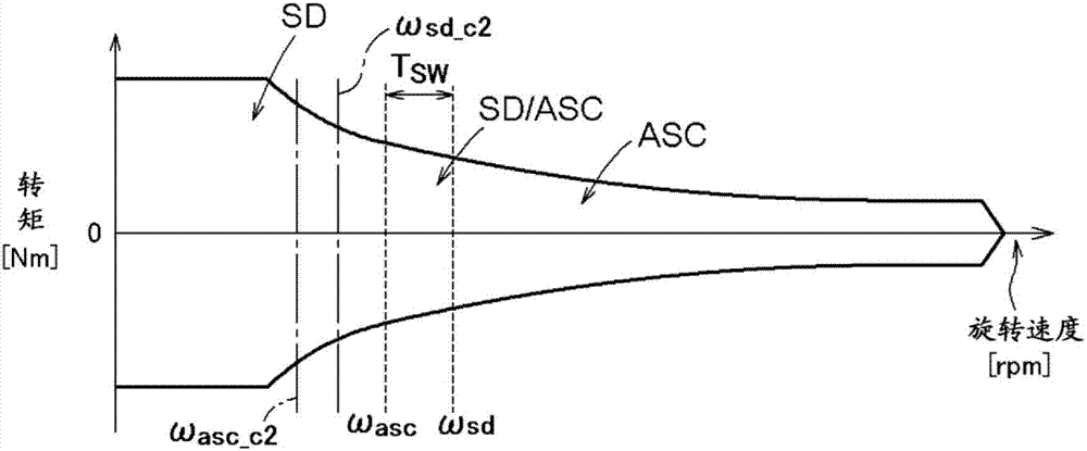
[0084] Next, a second embodiment of the inverter control device will be described. In the present embodiment, the inverter control device 20 selectively executes active short-circuit control (ASC) and shutdown control (SD) according to the modulation control method of the inverter 10 when the rotary electric machine drive device fails. This point is different from the first embodiment described above in which these controls are selectively executed according to the rotation speed of the rotary electric machine 80 . Hereinafter, the inverter control device 20 according to the present embodiment will be described focusing on differences from the first embodiment described above. In addition, about the point which is not demonstrated especially, it can be made the same as that of the said 1st Embodiment.
[0085] Also in the present embodiment, the inverter control device 20 is based on the target torque TM of the rotary electric machine 80 supplied as a request signal from anot...
no. 3 approach
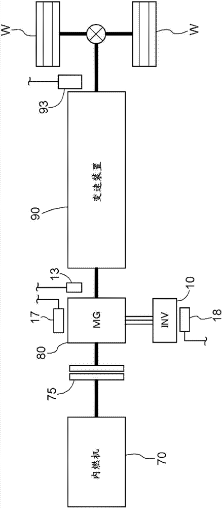
[0108] Next, as a third embodiment, an embodiment of a vehicle control device including the inverter control device according to the above-mentioned first embodiment or second embodiment will be described. Such as Figure 14 As shown, the vehicle control device 50 includes a vehicle drive device 60 including at least a rotary electric machine (MG: Motor / Generator) 80 and a transmission device 90 , and a rotary electric machine drive device 1 (INV) including the above-mentioned inverter 10 . control target. Therefore, it is constituted by including the above-mentioned inverter control device 20 for controlling the rotary electric machine drive device 1 . In the present embodiment, the vehicle drive device 60 is a so-called parallel type hybrid drive device, and includes an internal combustion engine 70 and a rotary electric machine 80 as a drive force source for the wheels W. That is, in the present embodiment, the vehicle drive device 60 includes an internal combustion engin...
PUM
 Abstract
Description
Claims
Application Information
 - R&D
- Intellectual Property
- Life Sciences
- Materials
- Tech Scout
- Unparalleled Data Quality
- Higher Quality Content
- 60% Fewer Hallucinations
Browse by: Latest US Patents, China's latest patents, Technical Efficacy Thesaurus, Application Domain, Technology Topic, Popular Technical Reports.
© 2025 PatSnap. All rights reserved.Legal|Privacy policy|Modern Slavery Act Transparency Statement|Sitemap|About US| Contact US: help@patsnap.com