A light beam shaping apparatus

A beam shaping and beam technology, applied in optics, optical components, instruments, etc., can solve the problems of short working distance, large divergence angle, and insufficient utilization of beam, and achieve the effect of reducing loss and improving shaping efficiency.

Pending Publication Date: 2017-09-01
SUZHOU INST OF NANO TECH & NANO BIONICS CHINESE ACEDEMY OF SCI
View PDF8 Cites 10 Cited by
  • Summary
  • Abstract
  • Description
  • Claims
  • Application Information

AI Technical Summary

Problems solved by technology

If only the ordinary microlens array beam shaping system is used, the collimated spot diameter will be smaller, the divergence angle will be larger, and the working distance will be shorter, the beam will not be fully utilized, and more light energy will be lost during transmission. Poor beam quality

Method used


Image

  • A light beam shaping apparatus
  • A light beam shaping apparatus
  • A light beam shaping apparatus

Examples


Embodiment Construction

[0022] Hereinafter, embodiments of the present invention will be described in detail with reference to the drawings. However, the present invention can be implemented in many different forms, and the present invention should not be construed as being limited to the specific embodiments set forth herein. On the contrary, these embodiments are provided to explain the principle of the present invention and its practical application, so that other skilled in the art can understand various embodiments of the present invention and various modifications suitable for specific anticipated applications.

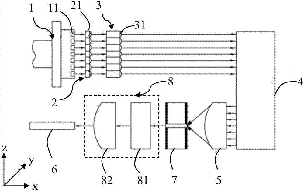
[0023] Reference figure 1 , The beam shaping device provided in this embodiment includes a light source 1, an exit light path (e.g., figure 1 In the x direction), the first lens array 2, the second lens array 3, the beam shaper 4, the beam concentrator 5, and the first optical fiber 6. The light source 1 includes a plurality of semiconductor lasers 11 arranged in an array, and the first l...


PUM


Abstract

The present invention provides a light beam shaping device comprising a light source and a first lens array, a second lens array, a light beam shaper, a light beam focusing device and a first optical fiber which are sequentially remote from the light source and disposed on an outgoing light path of the light source; the light source comprises a plurality of semiconductor lasers arranged in arrays; the first lens array comprises a plurality of first lenses arranged in arrays; the first lenses are aligned with the semiconductor lasers in a one-to-one corresponding mode; the second lens comprises a plurality of second lenses arranged in arrays; the second lenses are corresponding to the first lenses in a one-to-one mode; the light source is located in a front focal plane of the first lens array; and a back focal plane of the first lens array coincides with the front focal plane of the second lens array. The first lens array collimates the light of the light source in the direction of the fast axis, and the second lens array collimates the light of the light source in the slow axis direction. By collimating the light of the light source in the slow axis direction, loss on sides surfaces due to divergence in the slow axis direction is reduced, thereby raising the shaping efficiency.

Description

Technical field [0001] The invention relates to the technical field of semiconductor lasers, in particular to a beam shaping device. Background technique [0002] Semiconductor lasers are widely used in the first optical fiber communication, photoelectric integration, optical disk storage, pump light source, atmospheric environment detection, trace toxic gas analysis, molecular spectroscopy, etc. due to their small size, light weight, low voltage and high power. Many fields closely related to human life. However, due to its special working principle, the beam quality of semiconductor lasers differs greatly in the two directions perpendicular and parallel to the PN junction. Usually, the direction perpendicular to the PN junction is called the fast axis direction, and the direction parallel to the PN junction. This is called the slow axis direction. The beam divergence angle in the fast axis direction is large, and the beam divergence angle in the slow axis direction is small. ...

Claims


Application Information

Patent Timeline
Patent Type & Authority Applications(China)
IPC IPC(8): G02B27/09G02B27/30
CPCG02B27/0905G02B27/0961G02B27/0972G02B27/30
Inventor 杨立梅黄伟李丰张巍巍
Owner SUZHOU INST OF NANO TECH & NANO BIONICS CHINESE ACEDEMY OF SCI
Why Eureka
Try Eureka