Mixed density medium double-plastid vibration mill with convex springs without join of cycles

A technology of mixed density and coil spring, applied in grain processing and other directions, can solve the problems of high noise, low noise and low efficiency, and achieve the effect of simplified process, light weight and reduced energy consumption

Inactive Publication Date: 2017-09-08
NANJING INST OF TECH
View PDF10 Cites 1 Cited by
  • Summary
  • Abstract
  • Description
  • Claims
  • Application Information

AI Technical Summary

Problems solved by technology

[0008] The invention provides a convex type non-coil spring, mixed density medium single-tube dual-mass vibration mill, which has the technical characteristics of dual-mass, the main vibration spring is a convex non-coil spring, and the vibration isolation spring is rubber canvas composite Springs, main-vibration isolation springs are all variable stiffness; in order to increase the impact, extrusion, shearing, and collision energy of the grinding media balls in the cylinder during relative motion, the optimal setting of the mixed density medium ratio is implemented, which is widely used with existing Compared with the ordinary single cylinder vibrating mill system, it has the characteristics of high efficiency and low noise, and aims to effectively solve the technical bottleneck problems of high noise and low efficiency that have been pending for the existing vibratory mill.

Method used


Image

  • Mixed density medium double-plastid vibration mill with convex springs without join of cycles
  • Mixed density medium double-plastid vibration mill with convex springs without join of cycles
  • Mixed density medium double-plastid vibration mill with convex springs without join of cycles

Examples


Embodiment Construction

[0033] In order to deepen the understanding of the present invention, the present invention will be described in further detail below in conjunction with the accompanying drawings and embodiments, which are only used to explain the present invention and do not limit the protection scope of the present invention.

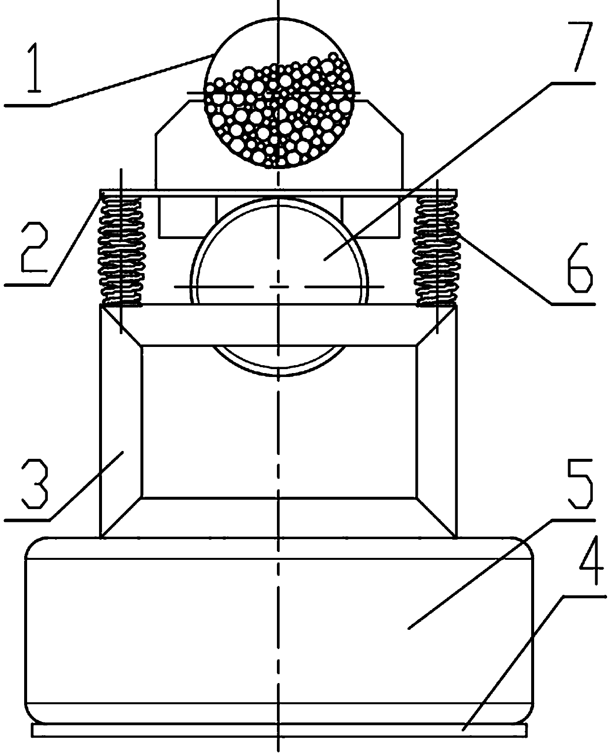
[0034] figure 1 Shown is a schematic diagram of the structure of the vibration mill of the present invention, which is mainly composed of a grinding cylinder 1, an upper plastid, 2, a lower plastid 3, a bottom plate 4, a vibration isolation spring 5, a main vibration spring 6, a vibration motor 7, etc. In this embodiment, the material to be ground and the grinding medium are installed in the barrel, and the filling coefficient is set to 65%. The grinding medium is wear-resistant steel ball and tungsten steel ball. The diameters are 2mm, 3.5 mm, 5 mm, 6.5mm, the material is ultra-hard fine powder, the vibration frequency of the mill is 1450 rpm, the measured amplitude...


PUM


Abstract

The invention provides a mixed density medium double-plastid vibration mill with convex springs without join of cycles. The vibration mill comprises a main vibration system and a vibration isolation system; the main vibration system comprises a vibration motor controlled by a frequency converter and used as an excitation source, and a milling cylinder fixed to the vibration motor; an upper plastid is made up of the vibration motor, the milling cylinder and an upper plastid plate, and one end of a lower plastid is connected to a main vibration spring set; the lower plastid is connected to the vibration isolation system through the main vibration spring set; the vibration isolation system comprises isolation springs connected to the other end of the lower plastid, and each isolation spring is connected to a foundation through a base; and the main vibration spring set is composed of a plurality of convex coil springs without join of cycles, and each spring is formed by winding a steel wire. The vibration mill provided by the invention has the characteristics of ultrafine particle refinement, disaggregation, narrowing of powder product distribution zone, low energy consumption, high grinding efficiency, high energy utilization rate, effective energy storage, energy saving, stable operation, obvious noise reduction, good vibration isolation effect, etc.

Description

technical field [0001] The invention relates to a grinding equipment for vibrating the preparation of superfine powder of materials. It is a single-tube dual-mass vibrating mill with a convex non-coil spring and a medium with a mixed density ratio. It belongs to the field of vibration utilization and Interdisciplinary science and technology of powder engineering. Background technique [0002] Vibrating mill is a vibrating mechanical equipment that uses the principle of vibration to complete the ultrafine grinding operation of materials. In the existing ultrafine powder preparation technology, vibrating mill and other preparation methods include gas phase synthesis, liquid phase synthesis, jet milling, Compared with the drum milling method, it has the advantages of high mechanical activity of the material, convenient purification, low cost, simple structure, and high efficiency. The existing vibrating mill support spring generally adopts a linear equal-pitch helical spring; i...

Claims


Application Information

Patent Timeline
Patent Type & Authority Applications(China)
IPC IPC(8): B02C17/10B02C17/14B02C19/16B02C23/00
CPCB02C17/10B02C17/14B02C19/16B02C23/00
Inventor 杨小兰刘极峰冯勇
Owner NANJING INST OF TECH
Why Eureka
Try Eureka