Automatic tool clamp of machine tool shaft pipe fittings

A tooling fixture and machine tool shaft technology is applied in the field of automatic tooling and fixtures for machine tool shafts and pipe fittings, which can solve the problems that the production efficiency cannot be improved, the machining performance of the machine tool cannot be improved, and the machining with a large amount of tools cannot be processed, and the positioning and clamping process is fast. Tight and relaxing time, protective safety effect

Inactive Publication Date: 2017-09-08
十堰市神针工贸有限公司
View PDF0 Cites 7 Cited by
  • Summary
  • Abstract
  • Description
  • Claims
  • Application Information

AI Technical Summary

Problems solved by technology

[0002] In today's era of rapid development, the processing of products is inseparable from the processing of machine tools. Using machine tools to process products can not only save labor time, improve work efficiency, but also reduce the labor intensity of workers, but machine tools have relatively high precision requirements for product processing. Strictly, the performance of a machine tool fixture will greatly affect the processing performance of the machine tool. When processing shaft pipe fittings, the traditional method is to use chuck fixtures and cone plug fixtures. Although manual clamping chuck fixtures can be Reduce the production cost of the machine tool, but this kind of fixture is time-consuming to clamp. The tailstock adopts a cone-type fixture. Due to the lack of rigidity of this kind of fixture, it is easy to vibrate during the machining process, which makes it deviate from the center hole and cannot be processed with a large amount of cutting. Production Efficiency cannot be improved

Method used


Image

  • Automatic tool clamp of machine tool shaft pipe fittings
  • Automatic tool clamp of machine tool shaft pipe fittings
  • Automatic tool clamp of machine tool shaft pipe fittings

Examples


Embodiment Construction

[0015] The following will clearly and completely describe the technical solutions in the embodiments of the present invention with reference to the accompanying drawings in the embodiments of the present invention. Obviously, the described embodiments are only some, not all, embodiments of the present invention. Based on the embodiments of the present invention, all other embodiments obtained by persons of ordinary skill in the art without making creative efforts belong to the protection scope of the present invention.

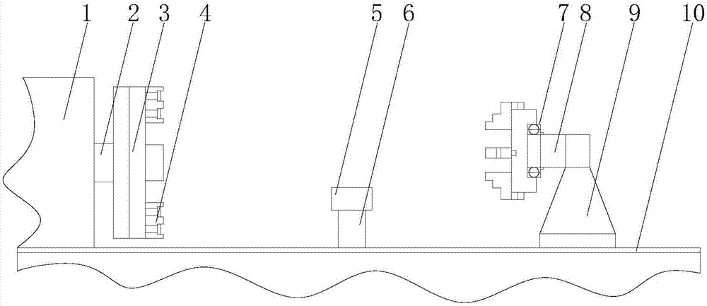
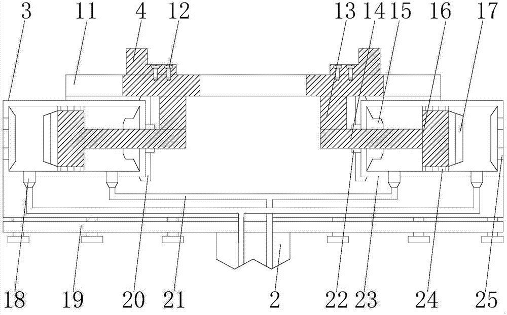
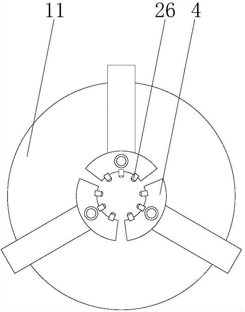
[0016] see Figure 1-4 , a kind of embodiment that the present invention provides: a kind of automatic tooling and fixture of shaft type pipe fittings of machine tool, comprise machine tool 1, concave support table 5, tailstock 9 and second guide rail 11, the right end of the rotating shaft 2 on the right side of machine tool 1 is fixed with The connecting plate 19 fixedly connected with the chuck body 3 by the fastening screw 12, and the right side of the chu...


PUM


Abstract

The invention discloses an automatic tooling fixture for machine tool shaft pipe fittings, which includes a machine tool, a concave support table, a tailstock and a second guide rail. The connecting plate is fixedly connected, and the right side of the chuck body is equipped with a claw with a clamping nail inside, the bottom end of the concave support table is installed with a hydraulic rod that is slidingly connected with the first guide rail, and the upper end of the tailstock The connecting rod and the inner ring of the bearing are fixedly connected, the slider inside the second guide rail is fixedly connected with one end of the piston rod through a fixed block, and the piston is fixed on the inner wall of the chuck body through a positioning block A sealing ring is installed between the cylinder blocks. The invention adopts the hydraulic cylinder to drive the claws to clamp the shaft pipe fittings, so that the positioning and clamping process is quick, and at the same time, a chuck is also arranged on the tailstock, which avoids the need to process the inner hole on the parts when clamping the shaft pipe fittings, saving working hours.

Description

technical field [0001] The invention relates to the technical field of tooling and fixture equipment, in particular to an automatic tooling and fixture for shaft and pipe fittings of machine tools. Background technique [0002] In today's era of rapid development, the processing of products is inseparable from the processing of machine tools. Using machine tools to process products can not only save labor time, improve work efficiency, but also reduce the labor intensity of workers, but machine tools have relatively high precision requirements for product processing. Strictly, the performance of a machine tool fixture will greatly affect the processing performance of the machine tool. When processing shaft pipe fittings, the traditional method is to use chuck fixtures and cone plug fixtures. Although manual clamping chuck fixtures can be Reduce the production cost of the machine tool, but this kind of fixture is time-consuming to clamp. The tailstock adopts a cone-type fixtu...

Claims


Application Information

Patent Timeline
Patent Type & Authority Applications(China)
IPC IPC(8): B23Q3/12B23Q1/76B23B31/16B23B23/00
CPCB23Q3/12B23B23/00B23B31/16287B23Q1/76
Inventor 郝兴强吴远林赵天财解春娥
Owner 十堰市神针工贸有限公司
Why Eureka
Try Eureka