Hybrid power unmanned aerial vehicle

A hybrid power and unmanned aerial vehicle technology, applied in the field of aircraft, can solve the problems of difficult real-time speed regulation, short endurance time, small load, etc., and achieve the effect of improving load and endurance time, high load and endurance time, and stable rotation speed

Inactive Publication Date: 2017-09-08
陶霖密
View PDF6 Cites 16 Cited by
  • Summary
  • Abstract
  • Description
  • Claims
  • Application Information

AI Technical Summary

Problems solved by technology

However, the shortcomings of UAVs based on brushless motors are also obvious. First, the motors with a kilowatt or more have a large rotor and large inertia, so it is difficult to adjust the speed in real time; second, the current lithium battery has a low energy mass density. Low man-machine load and short battery life
Gasoline and kerosene engines with high energy mass density are difficult to adjust speed accurately and quickly, making it difficult for existing multi-rotor UAVs to use traditional UAV power systems, such as gasoline engines and kerosene engines.
Therefore, the development of traditional multi-rotor drones has encountered great difficulties and requires new breakthroughs
[0007] Based on the above analysis, the main advantages of helicopters are large single (or double) rotors, variable pitch and angle, so that the rotors of the helicopter have both lift and control, and have the advantages of large load and high efficiency. However, it is too large Rotors cause high speed motion of the rotor tip relative to the air, resulting in increased drag and instability at the expense of efficiency and reliability
The advantage of multi-rotor is that the lift and control force of the aircraft come from multiple identical rotors. The simple structure brings simple control and high serviceability, but its load is too small to achieve high load, long range or long range. time, high wind resistance flight

Method used


Image

  • Hybrid power unmanned aerial vehicle
  • Hybrid power unmanned aerial vehicle
  • Hybrid power unmanned aerial vehicle

Examples


Embodiment 1

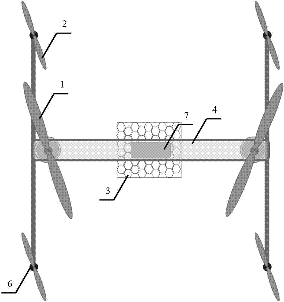
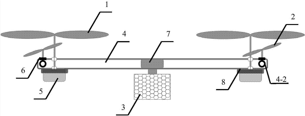
[0053] Embodiment 1: A hybrid six-rotor UAV with dual-fuel motors and direct-drive dual-blade rotors

[0054] Such as figure 1 , 2 , 3, shown in 4, a kind of hybrid power, hybrid six-rotor unmanned aerial vehicle, comprise two lift rotors 1, four control rotors 2, load frame 3 and frame 4 of symmetrical arrangement, described lift rotor 1, control Rotor 2 and load frame 3 are all installed on the frame 4. The lift rotor 1 is arranged on both sides of the central axis of the drone, and the rotor surface of the lift rotor 1 is perpendicular to the central axis of the drone; the lift rotor 1 is driven by a fuel motor 5; the lift rotor 1 directly Installed on the fuel motor 5. The control rotor 2 is driven by four electric motors 6 with identical parameters. The electric motor 6 is powered by a battery pack 7 . The fuel tank of the fuel motor 5 is equipped with a honeycomb thin-walled porous structure, which is used to eliminate the drone control problem caused by the sloshin...

Embodiment 2

[0066] Embodiment 2: A hybrid six-rotor UAV with dual-fuel motors driving dual-blade rotors through pulleys

[0067] The only difference between this embodiment and Embodiment 1 is that the fuel motor drives the two-blade rotor through the pulley, such as Figure 5 , 6 , shown in 7, a kind of hybrid power, hybrid six-rotor UAV, comprise two lift rotors 1, four control rotors 2, load frame 3 and frame 4, described lift rotor 1, control rotor 2 and load frame 3 are installed on the frame 4. The lift rotor 1 is arranged on both sides of the central axis of the drone, and the rotor surface of the lift rotor 1 is perpendicular to the central axis of the drone; the lift rotor 1 is driven by a fuel motor 5; the control rotor 2, It is installed on four electric motors 6 with identical parameters, and is driven by the electric motors 6 described above. The electric motor 6 is powered by a battery pack 7 . The fuel tank of the fuel motor 5 is equipped with a honeycomb thin-walled po...

Embodiment 3

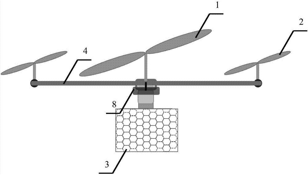
[0070] Embodiment 3: A hybrid power hybrid six-rotor UAV with a single fuel motor driving a dual-blade rotor through a pulley

[0071] The difference between this embodiment and Embodiment 2 is that the drive is changed from a dual fuel motor to a single fuel motor. Such as Figure 8 , 9 , shown in 10 and 11, a kind of hybrid power, hybrid six-rotor UAV, comprise two lift rotors 1, four control rotors 2, load frame 3 and frame 4, described lift rotor 1, control rotor 2 and The load frames 3 are all installed on the frame 4 . The lift rotor 1 is arranged on both sides of the central axis of the drone, and the rotor surface of the lift rotor 1 is perpendicular to the central axis of the drone; the lift rotor 1 is driven by a fuel motor 5; the control rotor 2, It is installed on four electric motors 6 with identical parameters, and is driven by the electric motors 6 described above. The electric motor 6 is powered by a battery pack 7 . The fuel tank of the fuel motor 5 is eq...


PUM


Abstract

The invention relates to a hybrid power unmanned aerial vehicle. The hybrid power unmanned aerial vehicle is characterized by comprising at least two lifting rotors, control rotors, a load frame and a rack, wherein the lifting rotors, the control rotors and the load frame are all mounted on the rack; the lifting rotors are symmetrically arranged in pairs and are arranged on two sides of the central axis of the unmanned aerial vehicle, and the rotor faces of the lifting rotors are perpendicular to the central axis of the unmanned aerial vehicle; and the lifting rotors are driven by fuel motors, and the control rotors are driven by motors. According to the hybrid power unmanned aerial vehicle, the lifting rotors provide the main lifting force; the control rotors keep the attitude of an aircraft; during advancement, retreatment and selective movement in a plane, the control rotors are accelerated or decelerated to change the attitude of the aircraft; the control algorithm of the unmanned aerial vehicle is similar to that of the multiple rotors, and a matched control structure of a helicopter is omitted, so that the structure and the control algorithm are greatly simplified, and further, the stability, the load, the flight duration and the controllability of the aircraft are improved.

Description

technical field [0001] The invention relates to an aircraft, in particular to a hybrid power hybrid rotor unmanned aerial vehicle. Background technique [0002] With the booming development of the drone industry, a variety of unmanned aerial vehicle systems have been invented to achieve different missions. Unmanned aerial vehicles are classified according to their appearance and flight principles. There are three main types: fixed-wing, helicopter, and multi-rotor. Among them, fixed-wing UAVs cannot take off and land vertically and hover, while helicopters and multi-rotor UAVs can take off and land vertically and hover. [0003] After theoretical analysis, multi-rotor drones, also known as multi-axis aircraft, including 4-rotor drones, 6-rotor drones and 8-rotor drones, are characterized by multiple identical rotors that rotate in pairs. , generating lift. At the same time, the speed difference between different rotors produces the inclination angle of the UAV to the grou...

Claims


Application Information

Patent Timeline
Patent Type & Authority Applications(China)
IPC IPC(8): B64C27/08B64C39/02B64D27/02
CPCB64C27/08B64C39/02B64D27/02B64D2027/026B64U50/11B64U10/10B64U50/19
Inventor 陶霖密
Owner 陶霖密
Why Eureka
Try Eureka